Lightweighting speed into CNC machining
Drawing on a long history in composites manufacturing and CNC machining, this innovator turns to carbon fiber composites to reduce gantry component weight and increase shaping efficiency.
Design results:
- Carbon fiber composite gantry yields weight savings of 90% compared to steel alternative.
- Linear composites manufacturing process speeds production by eliminating welding and powder coating associated with steel alternative.
- Lighter weight components on the y and z axes reduce cutting time by 50% compared to steel alternative, with no accuracy penalty.
Dan Bolfing has taken a circuitous career route from world-class windsurf board manufacturer to CNC machine manufacturer. But the path between those callings is clear in hindsight. His surfboard-making dates to the early 1990s. Over time, he saw the increasing application of advanced composites to surfboards, to make them lighter, stronger and more durable.
In the late 1990s, says Bolfing, he was living in Maui, HI, US, building windsurf boards and kiteboards and looking for affordable CNC technology to help speed up the previously manual process of shaping tooling board into molds for those evolving composite surfboard designs. He ran across an article in Composites Technology magazine (a predecessor of CompositesWorld) about CNC machining of composites and, as a result, invested in a ShopBot (Durham, NC, US) router. The simplicity and efficiency of that router, says Bolfing, “changed my life. It gave a small company access to Fortune 500 technology.” Yet, as capable as the ShopBot router was, Bolfing says he also started modifying it as soon as it was installed. That process taught him much about how CNC technology might be improved to make it more efficient, flexible and affordable.
Re-routing of career choice
In 2004, Bolfing suffered a serious injury and spent the next five years in recovery. He used that time to teach himself basic programming, and how to use CAD/CAM software. He also made plans for the rest of his life, which included relocation to the US mainland to launch a car company that would manufacture electric vehicles. Because Bolfing needed a CNC machine for this effort but could not afford one, he built his own. As he used that machine to build structures for his car, he did contract machining on the side to earn money.
He quickly saw the advantage of a bigger machine: “I built another, larger machine and sold my older one,” he says. “I soon saw the advantages of a larger machine and replaced the second machine with a third machine. As I got bigger, the parts had to be stiffer, using more steel.”
By 2010, Bolfing was the owner and operator of Autoscale CNC LLC (Santa Clara, CA, US), busy providing contract CNC services and selling his own brand of all-steel CNC machines. Although he could market the versatility and flexibility of a larger CNC machine, the problem was speed — or a lack thereof — which was compounded by the conventional machine’s dependence on its steel construction. “We were like a dog chasing its tail,” he says. “As the [CNC] machines got bigger, they got heavier, and as they got heavier, they got slower.” Having seen how well composites had performed in windsurf board and kiteboard applications, Bolfing began to wonder if there was a place for carbon fiber composites in the fabrication of a CNC machine.
Additionally, notes Bolfing, the all-steel CNC machines required extruded steel, which is expensive, as well as multiple high-skill processes — assembly, welding, powder coating. Each is costly and time-consuming, particularly in a skilled labor market as pricey as that in the San Francisco Bay Area, where Autoscale is located. In terms of labor and processing steps, Bolfing contends, “It’s a lot easier to build a composite CNC machine than a steel CNC machine.”
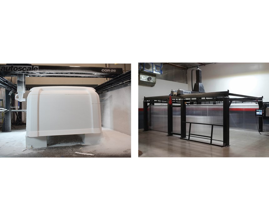
But applying composites to a CNC machine, which had not been done before, says Bolfing, would require substantial design, investment and time. So, the idea simmered in his head until 2015, when he began an earnest effort to apply carbon fiber composites in a CNC machine. The product that resulted — introduced in 2016 — is Autoscale’s carbon fiber-intensive Monster cgr-series machine (see photo), designed to process composites, foams, clays and lightweight metals.
The mettle to replace metal
As he designed the cgr-series, Bolfing decided early on to apply composites only where their greatest advantage, weight reduction, would increase speed — the y-axis gantry, the z-axis carrier and the z-axis arm. Other parts, namely the x-axis columns and beams, would be welded steel. “Everything that doesn’t move is steel,” he explains. “All the moving mass is carbon.”
Bolfing says he knew that speed would come naturally from the reduced weight of the composite y and z axes. The challenge would be the design and construction of a composite structure stiff enough to maintain the rigidity required in high-precision machining operations. “All three axes have to have equal support,” Bolfing says. “That was what I worked on first.”
Bolfing, who was the cgr-series’ sole designer, began in SolidWorks (Dassault Systèmes, Waltham, MA, US) and Rhino (Robert McNeel & Assoc., Seattle, WA, US), but confesses his virtual work on the composite structures eventually had to move to a more difficult shake down in the physical world: “There is only so much you can do, drawing in CAD. You eventually have to start building things.”
He focused first on the gantry and fabricated several 8- to 10-ft-long (2.4m to 3m) process panels, using multiple material combinations (UD and woven laminates) to test their weight-bearing capability and stiffness. Bolfing hung from the center of these test panels a variety of weights, measuring deflection with each, and using the results to guide further material combination refinements.
Then, says Bolfing, “I over-engineered it by about 10% .” Why? As is often the case with composites, massive weight savings convey to designers a margin that allows for use of additional material, with minimal penalty. A steel gantry, Bolfing notes, would weigh about 3,500 lb (1,588 kg). The carbon fiber gantry he designed to replace it weighs only 350 lb/159 kg, “so even if it’s 50% overbuilt, it’s still incredibly light.”
The resulting design consists of two parallel 8-by-8-inch (203 by 203 mm) box beams 14.5 ft/4.72m long, featuring aramid honeycomb, aluminum honeycomb and Divinycell (DIAB Americas LP, DeSoto, TX, US) foam core overwrapped on three sides with dry unidirectional (UD) carbon fiber, topped by an outer ply of woven carbon fiber twill. The fourth side of each beam is covered with a carbon fiber composite lattice structure, to provide access to wiring that must pass through the beam. All carbon
fiber is supplied by Hexcel (Stamford, CT, US). The two beams are connected at each end by a 16-inch/406-mm carbon fiber composite beam, similarly constructed. Total width of the gantry is 32 inches/812 mm. Mounted on each long beam is a steel rail, on which rides the z-axis carrier and the z-axis arm (see the photo on p. 46).
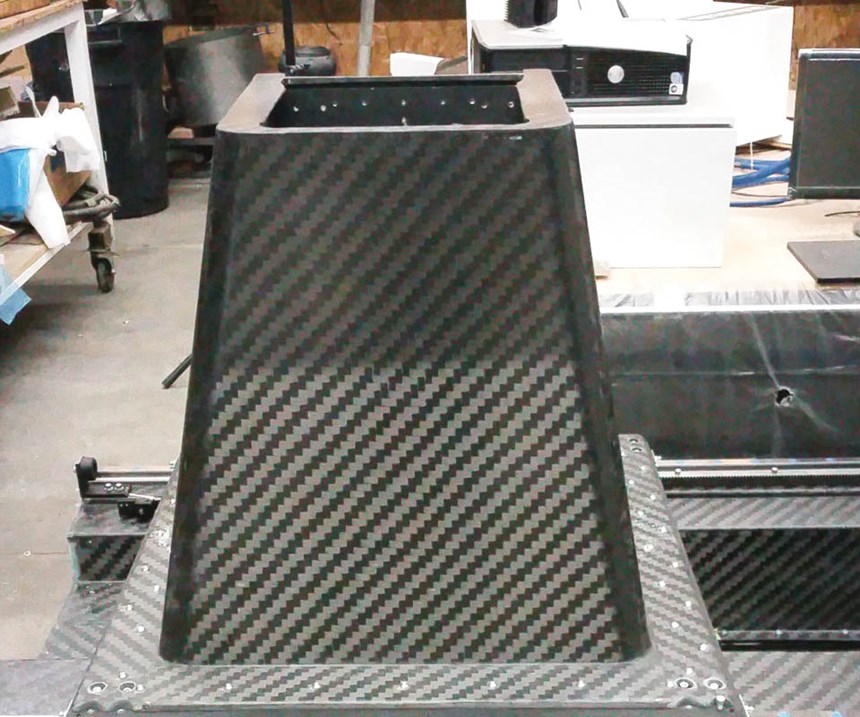
The z-axis arm traverses the gantry supported vertically within the z-axis carrier, a tapered carbon fiber box with a 32-by-32-inch (812 by 912-mm) flange at its base (photo above), which rides on the y-axis rails. The z-axis arm sits in and is actuated through the carrier by a servomoter mounted at the top of the z-axis arm (see drawing, above).
Bolfing used the same sandwich architecture on the z-axis carrier and z-axis arm — core surrounded by UD and woven carbon fiber. And, like the gantry, all of the layups are infused with epoxy supplied by Pro-Set Inc. (Bay City, MI, US) and Gurit (USA) Inc. (Bristol, RI, US) through distributors Revchem Composites Inc. (Bloomington, CA, US) and Fiberglass Supply (Burlington, WA, US).
Bolfing also built the molds for the gantry parts from carbon fiber/epoxy composite, laid up on a Coastal Enterprises Co. (Orange, CA, US) 10-lb/4.5-kg urethane tooling board pattern. Cure is provided by Bolfing’s in-house-built, gas-fed oven, which features an adjustable enclosure, designed to enclose a space 4 ft/1.2m wide and 8-24 ft (2.4-7.3m) long.
A distinguishing design feature of the z-axis arm, says Bolfing, is the fact that its actuating equipment — motor, wiring, etc. — is encapsulated inside the arm, protecting it from dust generated during the machining process. And to further ameliorate dust, Bolfing applies an anti-static spray to the z-axis arm’s exterior.
Able performer, in demand
The z-axis arm on the cgr-series has a downward travel limit of 6 ft/1.8m, the gantry is 12 ft/3.6m long and the x-axis metallic frame is available in lengths of 10-35 ft (3-7.62m). Bolfing says the machine’s accuracy, over 27 ft/8.2m, is ±0.0625 inch (±0.15875 mm). Further, he claims, “No other machine has travel as large for such a small footprint. It makes excellent use of space.” The machine ranges in price from just US$80,000 for the smallest footprint, to US$160,000 for the largest.
In operation, the cgr-series machinery is more accurate, travels more smoothly and performs high-detail shaping better than Bolfing expected. Further, he anticipated that 14-lb/6.35 kg foam would be the densest the cgr-series could handle, but he reports that the machine “cuts through 20-lb [9-kg] foam like it’s nothing.”
Bolfing sold three machines before the first one was completed (“which is pretty scary”) and he delivered eight in the first year. Four more will be installed this month. Many, he says, are being used by customers 24/7 in lights-out operations and have performed without any problems. He is sufficiently confident now that his design and workmanship are sustainable that he is evaluating integration of other technologies to be offered with the machine, including a 4-axis rotisserie, a touch probe, a laser scanner, an additive manufacturing system and a fiber/tape placement head.
Most of all, however, Bolfing wants to keep his system affordable and, therefore, easily accessible to small and start-up businesses that desire versatile, accurate, durable CNC technology. “In our business, most of your money is made in meeting critical deadlines,” he contends. “And you need affordable, big machines to do multiple operations to meet those deadlines.”
Related Content
The Native Lab launches composites course training membership plan
Courses that touch on the fundamentals of composite materials, design, analysis and more are available for individuals and companies alike through TNL’s online platform.
Read MoreToray, University of Chicago speed up polymer recycling R&D
A jointly developed multi-scale computational predictive technique can accurately predict viscoelasticity from the chemical structures of polymers, ramping up product maturation.
Read MoreASCEND program update: Designing next-gen, high-rate auto and aerospace composites
GKN Aerospace, McLaren Automotive and U.K.-based partners share goals and progress aiming at high-rate, Industry 4.0-enabled, sustainable materials and processes.
Read MoreNew online training course targets prepreg basics
JEC World 2024: Composites Expert highlights how its E-Learning Composites Academy platform supports flexible industry learning with new courses developed with Stelia Aerospace North America.
Read MoreRead Next
Developing bonded composite repair for ships, offshore units
Bureau Veritas and industry partners issue guidelines and pave the way for certification via StrengthBond Offshore project.
Read More“Structured air” TPS safeguards composite structures
Powered by an 85% air/15% pure polyimide aerogel, Blueshift’s novel material system protects structures during transient thermal events from -200°C to beyond 2400°C for rockets, battery boxes and more.
Read MoreAll-recycled, needle-punched nonwoven CFRP slashes carbon footprint of Formula 2 seat
Dallara and Tenowo collaborate to produce a race-ready Formula 2 seat using recycled carbon fiber, reducing CO2 emissions by 97.5% compared to virgin materials.
Read More


