
Neat resin specimen fabrication aids
To obtain quality experimental data, one must have access to quality test specimens.
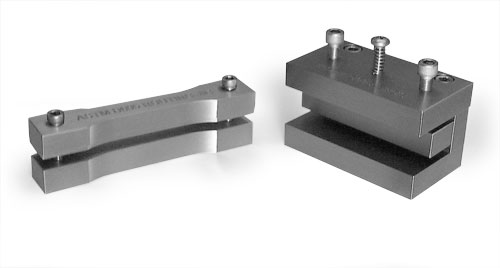
Fig. 3: Simple specimen contouring and end-routing jigs. Source: Don Adams
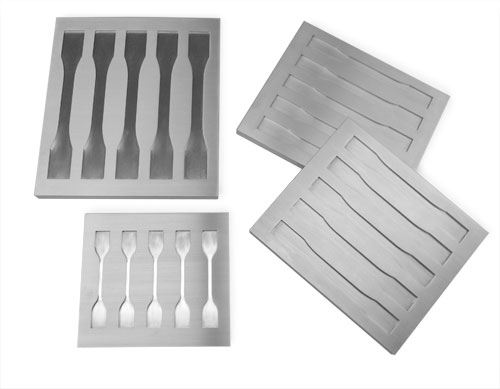
Fig. 1: Four different five-cavity resin casting molds. Source: Don Adams

Dr. Donald F. Adams is the president of Wyoming Test Fixtures Inc. (Salt Lake City, Utah). He holds a BS and an MS in mechanical engineering from, respectively, the University of Illinois and the University of Southern California, and a Ph.D in theoretical and applied mechanics from the University of Illinois. Following a total of 12 years with Northrop Aircraft Corp., the Aeronutronic Div. of Ford Motor Co. and the RAND Corp., he joined the University of Wyoming, directing its Composite Materials Research Group for 27 years before retiring from that post in 1999. Dr. Adams continues to write, teach and serve with numerous industry groups, including the test methods committees of ASTM and the Composite Materials Handbook 17 (CMH-17).
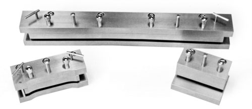
Fig. 2: A bowtie tensile specimen routing jig (top), the ASTM D 695 compression specimen dogbone routing jig (left), and a compression specimen end-routing jig (right). Source: Don Adams


To obtain quality experimental data, one must have access to quality test specimens. Toward that end, we’ll discuss the merits of two types of fabrication aids that are commonly used to produce neat resin specimens (that is, unreinforced polymer-matrix specimens): resin casting molds and routing jigs.
Casting molds are commonly used to prepare neat thermoset resin specimens for testing. Mold construction differs for flat and irregularly shaped specimens, and there is more than one option for each type.


For flat specimens, a common option is a multiple-cavity mold, such as those shown in Fig. 1, that is, a flat plate with the desired contours of the finished specimens machined into one surface. Aluminum is typically used to make the mold because of its high thermal conductivity and the relative ease with which it can be machined. Specimen thickness is governed by the depth of the machined contours, or, if it is a deep-cavity mold, by the extent of filling. Because the mold is open-faced, air bubbles that are trapped during mixing or generated by volatiles that evolve during vacuum degassing of the fluid resin have a short path to the free surface and, thus, are readily removed. Self-leveling of the fluid results in reasonably uniform specimen thicknesses. The result is a specimen ready for testing.
Another strategy is to cast a large, flat plate of the neat resin in an open mold and then machine individual specimens from it (machining is discussed later). It is particularly important in this case to have an effective release agent on the mold surfaces so that the cast resin plate does not stick, even locally, and thus result in cracking of the plate during cooldown from the resin cure temperature. Also, the machining operation adds significant additional cost to specimen preparation.
A third strategy — an alternative to open molding — is to cast a large, flat plate between two vertical surfaces that are spaced a fixed distance apart and sealed around three sides, leaving only the top edge open. It is convenient to use two sheets of glass as the basis for this mold because the cast material can be continually observed, if desired. Casting the specimen between two surfaces theoretically ensures constant plate thickness and smooth, flat surfaces. However, trapped volatiles (retained because of the long migration path some bubbles must travel to reach the mold’s open top edge) could cause voids, and nonuniform rates of resin shrinkage during cure could cause the plate to pull away from the mold surface in local regions, creating surface irregularities and stress concentrations in the casting. Also, adhesion to the two surfaces of the mold during cooldown from the casting temperature, even if slight, can cause the resin plate to crack (because the cured neat resin is not very strong).
For other than flat specimens — for example, dog-boned specimens of circular cross section — thick bars or plates can be cast in an open mold and subsequently machined to the desired circular cross-sectional shape. However, an alternative is to cast a cylinder of silicon rubber around a pattern of the desired specimen configuration (or use an existing specimen itself as the pattern) and then slice open the silicon rubber mold longitudinally to remove the pattern. Neat resin specimens then can be cast in this rubber mold and easily popped out when the mold is flexed open longitudinally after resin cure. Resin adhesion to the compliant mold surface during cure is not much of a concern, but air bubble entrapment can be a problem because the migration path to the open top of the mold can be lengthy. It is important to have the resin thoroughly degassed prior to pouring it into the mold.
When flat specimens are machined from a flat plate, often a router is used, not only for thermoset and thermoplastic neat resin specimens but fiber-reinforced composite specimens as well. A strip of the specimen material wider than the finished specimen is clamped in a jig that is contoured to the desired shape. The router’s cutting tool (the router bit) follows this contour as the jig is manually moved back and forth while in contact with it, shaping the specimen.
Several types of routing jigs are used. In one type, shown in Fig. 2, the specimen is contoured in two steps: The tee pins are first removed and a sufficiently wide strip of specimen material is pushed against the back of the jig. Then a clamping plate is pressed against the strip by tightening the screws. After the exposed edge of the strip is routed to the desired contour, the clamping plate is released and the specimen is removed. The tee pins are then reinserted, and the just-routed edge of the strip is indexed against them. The clamping plate is again tightened down, and the opposite edge is routed to complete the contour machining.
A simpler routing jig, shown on the left in Fig. 3, shapes specimen contours in a single step. Here, the strip of specimen material is clamped between two contoured plates, which permits both edges to be routed before the completed specimen is removed. This simple jig is thus faster to use than those in Fig. 2. However, one limitation is that the clamping screws are located beyond the ends of the specimen. Thus, for very long specimens it is more difficult to clamp the strip uniformly along its length. If the specimen has a relatively narrow gauge width and/or is relatively thin, it may slip and/or deflect due to the pressure of the router bit against it. As a result, the machined shape could be inaccurate. Fortunately, this isn’t a problem for most specimen configurations.
The routing jig at the right in Fig. 3 is used to machine specimen ends, when required. This type of jig is used primarily for preparing end-loaded compression specimens for which the specimen end surfaces must be very flat and parallel to each other. The specimen, after contour routing using one of the jigs previously mentioned, is then inserted in the end-routing jig, indexed against the back, and held in place by tightening the clamping plate using the two outside screws. The spring-loaded center screw passes through the top of the jig and is threaded into the clamping plate (the compressed spring around its shaft pushes against the screw head to raise the clamping plate up out of the way when the clamping screws are loosened).
Routing jigs are frequently exposed to water-based coolants during the routing operations, so stainless steel is commonly used to fabricate them to prevent rust and corrosion. Also, they don’t come in one-size-fits-all configurations. Because there are many different router machine configurations, each having a different diameter and location for the router bit and follower, routing jigs must be designed for the particular router machine to be used.


Related Content

Carbon fiber, bionic design achieve peak performance in race-ready production vehicle
Porsche worked with Action Composites to design and manufacture an innovative carbon fiber safety cage option to lightweight one of its series race vehicles, built in a one-shot compression molding process.
Read More
Improving carbon fiber SMC simulation for aerospace parts
Simutence and Engenuity demonstrate a virtual process chain enabling evaluation of process-induced fiber orientations for improved structural simulation and failure load prediction of a composite wing rib.
Read More
Optimizing a thermoplastic composite helicopter door hinge
9T Labs used Additive Fusion Technology to iterate CFRTP designs, fully exploit continuous fiber printing and outperform stainless steel and black metal designs in failure load and weight.
Read More
Nine factors to consider when designing composites cure tooling
Gary Bond discusses the common pitfalls and compromises when designing good cure tooling and their holistic significance for a robust composite production process.
Read MoreRead Next

Unidirectional composite axial tensile specimens
Dr. Don Adams explains why the design of tensile test coupons is more art than science, and explains the implications of that art for testing accuracy.
Read More
All-recycled, needle-punched nonwoven CFRP slashes carbon footprint of Formula 2 seat
Dallara and Tenowo collaborate to produce a race-ready Formula 2 seat using recycled carbon fiber, reducing CO2 emissions by 97.5% compared to virgin materials.
Read More
“Structured air” TPS safeguards composite structures
Powered by an 85% air/15% pure polyimide aerogel, Blueshift’s novel material system protects structures during transient thermal events from -200°C to beyond 2400°C for rockets, battery boxes and more.
Read More