Nondestructive inspection: Better, faster and cheaper
Faced with new time and cost pressures, NDI system suppliers are integrating inspection with manufacturing to reduce its share in part cost and cycle time.
Innovation is often a result of the push and pull of market forces: new products or applications that push forward in one industry can pull in their wake significant technological innovations in a closely related field. Such is the case with nondestructive inspection (NDI) technology. Historically slow and costly, NDI accounts for as much as 25 percent of the cost of manufacturing high-end aerospace parts. These costs were viewed as an unpleasant necessity and could be absorbed in big-budget, cost-plus military programs. But the advent of the Boeing 787 Dreamliner and Airbus A350 programs sparked rapid expansion of the commercial aircraft composites market, where production deadlines and price points are much less forgiving. The aerospace composites manufacturers who serve the commercial aircraft market are seeking more efficient, cost-effective inspection. And in response, NDI systems suppliers are working with customers to commercialize systems that incorporate entirely new approaches or step changes that represent significant improvements in utility, speed and cost.
Robotized NDI for complex geometries
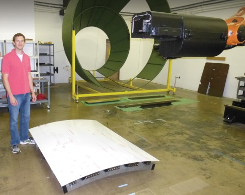
A number of companies are supplying equipment and services for what is the first large-scale, industrial implementation of a new type of NDI, called Surface-Adaptive, Phased-Array Ultrasound, or Surface-Adaptive ULtrasound (SAUL) for short. SAUL integrates robotics and ultrasound scanning, and uses a unique, surface-adaptive algorithm to conduct faster, more accurate inspections of composite parts that have complex shapes and sharp radii. SAUL enables, for the first time, the inspection of curved parts with a single, flat multi-element matrix probe. Contour Dynamics Inspection Systems (Lévis, Quebec, Canada) is the system designer, integrator and manufacturer. One unit already is installed at EADS Composites Aquitaine (Salaunes, France) and has been used to inspect several shipsets of carbon fiber parts for the Airbus A350. Each shipset comprises several hundred parts with dimensions up to 700 by 200 by 200 mm (27.5 by 7.9 by 11.8 inches), with thicknesses of 1 to 9 mm (0.039 to 0.354 inch), and both convex and concave radii with curvatures that vary from 4 to 7 mm (0.157 to 0.276 inch). Defects of interest are delaminations greater than 6 mm (0.236 inch) in diameter and in-plane porosity greater than 2 percent — both are thresholds for part rejection. The goal is an average inspection time of four minutes or less per part. Although SAUL is now used to inspect relatively small, thin parts, it can be adapted to inspect larger parts, including long fuselage stiffeners and frame sections.
“The aerospace business has changed, and we have many more parts with complex shapes ... than we used to have,” says Michel Brassard, a consultant who is under contract to Contour Dynamics to assist with the inspection implementation. “Today, NDI must become more fully integrated with the design and manufacturing process to meet requirements for efficiency and cost control.”
Adopting and adapting technologies
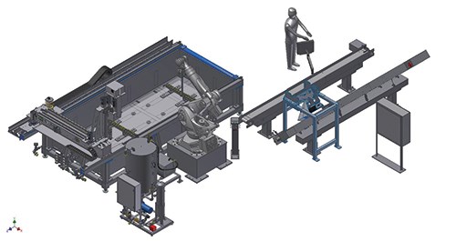
The SAUL technology now in use at the EADS subsidiary incorporates three distinctive functions, each intended to improve the efficiency of inspection and reduce the overall cost by more fully integrating it into the manufacturing process, which includes provision for part recognition, automated part placement and removal, and robotic ultrasonic scanning incorporating surface-adaptive software. SAUL incorporates nine essential pieces of equipment (see SAUL workcell diagram in second image form top, at left):
- Two conveyors for loading and unloading parts, and a part rotator.
- A 5-axis robot supplied by Kuka Robotics Corp. (Augsburg, Germany, and Shelby Township, Mich.).
- Two cameras for part shape recognition and bar code identification.
- A 5-axis robotic immersion scannner (4.5m by 1.9m by 0.8m/14.8 ft by 6.2 ft by 2.6 ft) built by Contour Dynamics Inspection Systems (Levis, Quebec, Canada, and Wichita, Kan.).
- A 3-D SINUMERIK contour controller supplied by Siemens Process Industries and Drives (Munich, Germany, and Alpharetta, Ga.).
- A 2-D, phased-array, multi-element matrix probe supplied by IMASONIC (Voray sur l’Ognon, France).
- A 64-channel MultiX, ultrasonic phased-array controller with SAUL surface-adaptive software supplied by M2M (Les Ulis, France).
Prior to inspection, the CAD drawing for each part (drawn in CATIA, from Dassault Systèmes, Vélizy-Villacoublay, France), is imported into Mastercam path-generating software (from CNC Software, Tolland, Conn.) to generate a scan plan. The geometric design data for each part is converted into CNC codes, which, via the SINUMERIK controller, direct the 5-axis scanner during inspection. Thus, the scanning plan is much like the tooling paths generated from the CAD drawings that are imported, via a CAM system, into CNC-machining systems. During the implementation, but prior to actual inspections, Contour Dynamics and EADS carried out extensive testing, checking and fine-tuning the scan paths to ensure that the efficiency and quality of the inspection were optimized.
During operation, the robot retrieves a part from the feed conveyor and presents it to the digital cameras, which identify the part by the Datamatrix 2-D bar codes on the part’s surface. Each bar code corresponds to a part number that is, in turn, categorized or coded by shape. The part shape determines, via internal programming, specifically where the robot will place it on the inspection table within the immersion tank. There are two inspection tables, or zones, located at each end of the tank. Within each table there are six subzones, each of which accommodates parts in a variety of generic shapes. The robot places the part on suction cups in the correct zone in the tank (±0.2-mm or ±0.010-inch accuracy), then the 5-axis scanner moves into position to commence scanning. Meanwhile, the robot moves to another zone to retrieve the part that the scanner has finished scanning, places it on the output conveyor, picks up a new part and repeats the cycle.
Several technologies were adopted and optimized for use in SAUL. Chief among them is M2M’s integration of the surface-adaptive algorithm into its ultrasonic phased-array controller. The patented technique was originally developed by the Commissariat à l’énergie atomique (CEA) in France for systems used to inspect the steel walls of reactors, containment vessels and other components in nuclear power plants.
The alternative to SAUL is to use curved arrays to inspect parts with complex shapes, such as hat stiffeners and stringers, that include convex and concave radii. This approach is problematic, however, because it requires extremely precise and consistent positioning of the probe along the entire length of the part to obtain valid measurements. Unfortunately, the slight part-to-part variability associated with composites manufacturing can pose a challenge to the precise positioning of curved arrays when parts are inspected in high volumes. That’s why SAUL, by means of its incorporated algorithm, uses a single flat matrix probe (located at the end of the 5-axis immersion scanner), comprising an array of 4 by 16 ultrasonic elements.
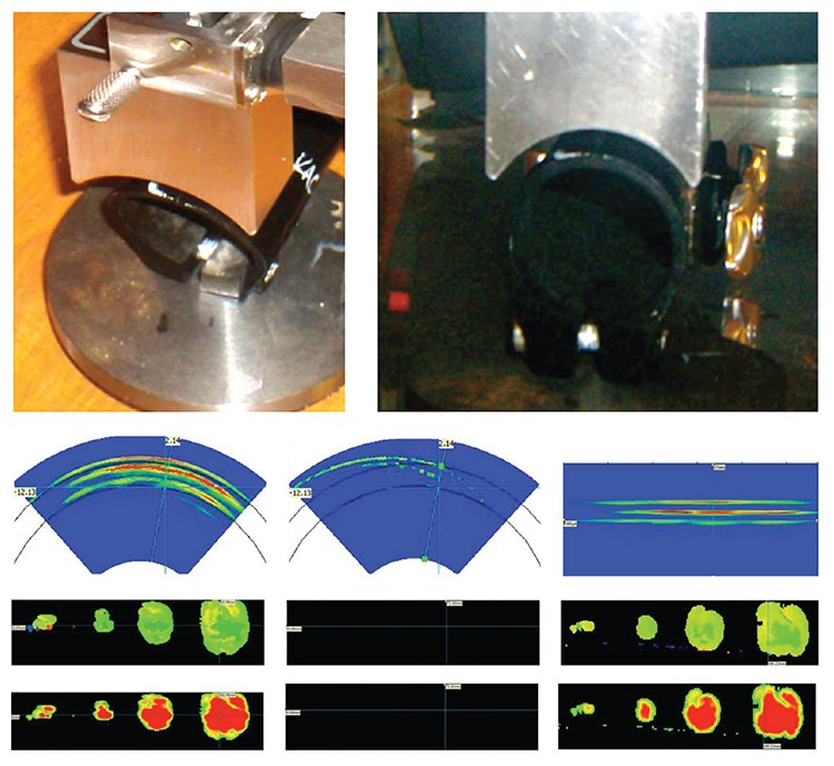
The M2M controller includes all the electronics needed to generate the electrical pulses to the probe’s elements, calculate and apply time delays to the elements to focus, steer and electronically scan the ultrasonic beam, receive the return signals and process and display the data. When SAUL is applied, the elements of the probe are fired in transmission without focusing, and the shape of the specimen is measured from the front-surface echoes. Next, an iterative, algorithm-controlled process is applied that calculates time delays in real time, adapted to the part geometry to transmit an incident wave that is normal to the surface (see diagrams at left). The system records and displays time-of-flight and amplitude data in both B-scans (vertical cross-sections through the specimen) and C-scans (horizontal or top views though the specimen). Raw amplitude vs. time data is translated into 2-D and 3-D images.
The ability of the surface-adaptive algorithm to compensate for changes in surface geometry was demonstrated in a series of tests conducted prior to the implementation of the SAUL inspection system at the EADS facility. In one experiment a conventional curved ultrasonic array was precisely positioned over a carbon fiber composite bike steering column, which contained release film discs in the laminate to simulate delamination defects of less than 0.25, 0.25, 0.5 and 0.75 inch (less than 6.35, 6.35, 12.7 and 19.05 mm) in diameter (see image at lower left). As long as the position of the probe with respect to the curvature of the tube was maintained precisely (i.e., normal to the surface) good results were obtained in the B-scans and C-scans (See images on p. 35). Shifting the probe by 3 mm/0.12 inch in any direction, however, resulted in loss of signal. With the probe in the shifted position, the surface adaptive algorithm was turned on. This restored the signal and matched the resolution of the scans obtained when the probe was positioned correctly.
Although no formal tests have been run to compare the efficiencies and inspection costs achieved by SAUL with those obtained by conventional phased-array or other NDI methods, Deborah Hopkins, CEO of M2M’s U.S. distributor, BERCLI Corp. (Berkeley, Calif.), says the surface-adaptive technology provides a number of clear benefits. For example, the use of conventional phased-array ultrasonic methods to inspect a single hat stiffener would require a minimum of five arrays — two curved arrays at the radii and three flat arrays for the top and sides. Additionally, the mandate for precise positioning of the probes, and part-to-part variability, usually requires much manual tweaking of fixtures, software and scan plans, which adds more time and cost.
Hopkins claims the integration of the surface-adaptive software into ultrasonic inspection is a boon for the aerospace composites industry. “The technology is not trivial, and the real trick is to do it on the fly, in real time,” she says. “It’s a dream come true for designers and manufacturers because now you can truly optimize strength-to-weight on a centimeter to centimeter basis, and efficiently inspect the part you’ve built.” Thus far, the program is exceeding its inspection time goal of one part every four minutes, with an actual inspection rate of one part every 2.5 minutes.
Laser ultrasonics gaining commercial acceptance
Like phased-array ultrasonic imaging technology, laser ultrasonic inspection systems have been on a development curve that has spanned several decades. In the 1990s, Tecnar Automation Ltée (St-Bruno, Quebec, Canada) became the first licenser of large-scale, commercial, industrial laser ultrasonic technology used for inline wall-thickness measurement of seamless steel tubes. Lockheed Martin is credited with commercializing the first laser ultrasonic NDI test system for composite part inspection. Today, the technology, as it pertains to composites, is closer to new applications in the commercial aerospace market. Companies that sell laser ultrasonic units for composite component inspections include Tecnar, iPhoton Solutions LLC (Fort Worth, Texas) and PaR Systems Inc. (West Shoreview, Minn.), which took over the technology developed by Lockheed Martin (Bethesda, Md.) for the F-35 Joint Strike Fighter program.
In a generic configuration, a laser ultrasound device comprises two lasers. One is a short-pulsed laser that generates an ultrasound wave in the surface of the composite material; the second is a single-frequency, high-coherence-length beam focused on or near the point of impact of the generation beam on the surface of the material. Any ultrasonic surface displacements that occur are encoded as frequency or phase variations in the reflected or backscattered light and are then converted into pulse-echo signals by an optical interferometer.
The principal advantage of laser ultrasonic inspection is that the generation laser beam does not need to be perpendicular (90°) to the material surface. The angle of incidence can, in fact, be as great as 45°. The inspection point (where the two lasers meet on the part surface) is indexed point by point over the material with an optical scanner to produce 2-D and 3-D ultrasonic images of the material. Because the scanner does not have to maintain a specific or consistent distance from the part surface, the system achieves inspection turnarounds on parts with complex shapes faster than those obtained with conventional, water-based ultrasound NDI systems that require upfront programming of the part shape into the scanner controller. Although laser ultrasonic NDI technology has been used in a variety of military and aerospace programs, including NASA’s Space Shuttles, it has yet to be fully qualified for large-scale commercial airline programs.
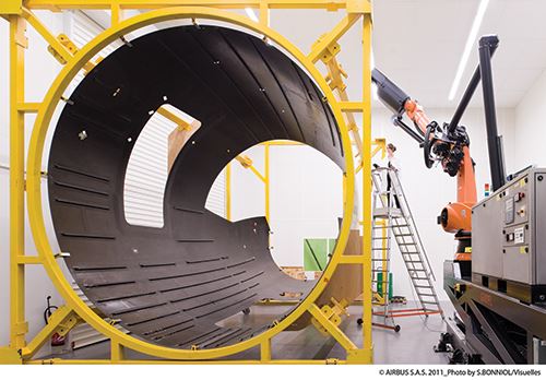
Supplier iPhoton Solutions manufactures a line of three CO2 laser ultrasonic NDI systems for composites inspection. The company’s iPLUS III model is currently undergoing qualification trials at Technocampus (Pays de la Loire, France) as one of the key components of a noncontact NDI system called LUCIE (see opening photo), developed in collaboration with Airbus Nantes (Nantes, France) and EADS Innovation Works (Ottobrunn, Germany).
Tommy Drake, iPhoton CEO, reports that the key differentiator of the company’s patented NDI technology is the use of commercial off-the-shelf articulated robots mounted on linear rails to move and position the optical scan head, rather than a large custom gantry robot like those employed in other laser ultrasonic systems. Drake claims the integration of commercial robots reduces the system’s footprint, installation foundation requirements, installation time and cost. The iPLUS III system for Technocampus’ LUCIE has a 6-axis KUKA robot capable of penetrating more than 6m/19.7 ft into the interior of demonstrator fuselages now undergoing inspection as part of the program. Drake says the inspection rate of the system is about 64 ft2/hr (about 6 m2/hr). “A single inspection area can be fairly large, for example, 5 ft by 5 ft [1.52m by 1.52m], during which the robot remains stationary,” he says. “The robot can then be indexed to another inspection area.”
Clay McConnell, VP communications at Airbus North America (Herndon, Va.), says the benefits of LUCIE compared to other NDI systems (including those equipped with ultrasonic phased arrays) are the elimination of the coupling media (water) and programming and tooling associated with keeping the scan head in precise position relative to the surface.
McConnell says the validation program is on track, and researchers expect to complete the evaluation of the benefits (laser vs. other ultrasonic systems) in 2014. “We need first to understand the way the laser interacts with each specific carbon fiber laminate used in the manufacturing of Airbus aerospace parts,” he says. “After this qualification process, there will, of course, be other activities to improve the performance of the technology — scanning speed, quality of signal, etc.”
Recently, iPhoton inspected composite test panels subjected to impact testing for the Federal Aviation Admin.’s (FAA) Airworthiness Assurance NDI Validation Center at Sandia National Laboratories (Albuquerque, N.M.). Tests performed by Sandia’s Infrastructure Assurance and Non-Destructive Inspection Dept. will produce data that will be used to evaluate a variety of NDI technologies.
Sandia fabricated two full-scale carbon-fiber fuselage sections, approximately 56 inches by 76 inches (1,422 mm by 1,930 mm). Each featured a 16-ply laminate and included cocured hat-section stringers and shear ties. The panels were fabricated from T800 unidirectional prepreg (Toray Composites (America) Inc. , Tacoma, Wash.) and autoclave cured. The panels are representative of laminates used on transport-category aircraft.
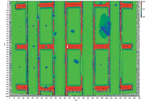
Simulated hail impact testing was conducted on the panels using 2.4-inch/61-mm ice balls and 2-inch/51-mm diameter steel-tip impacts. Using its iPLUS III laser ultrasonic NDI system, iPhoton conducted a C-scan inspection of the first panel, the results of which are shown and explained at the top of this page. As HPC went to press, Sandia was completing its testing report. However, iPhoton president Marc Dubois reports the total time for the inspection was about 45 minutes, which included preparation, and the data was considered of the highest quality.
Dubois says that iPLUS systems could appear in production facilities within two years, noting that the time span is due to the fact that the process for new technology approval on commercial aircraft can be more difficult than for military programs. “It takes a lot of time and effort to get a new technology qualified,” Dubois says, but adds, “It’s worth it, because we think our technology can reduce inspection cost by a factor of 10 for complex parts.”
In October 2012, Tecnar entered into an agreement to assist the Beijing Aeronautical Manufacturing Technology Research Institute (BAMTRI, Beijing, China) as it develops a knowledge base in laser-ultrasonic composite inspection.
“Because BAMTRI is a research institute, they are not looking for an industrial system, such as our Laser Ultrasonic Inspection System (LUIS), but rather at smaller laboratory-scale systems we offer, such as the TWM model,” says Marc Choquet, Tecnar’s VP, Laser-NDE. He continues, “We are still in the initial stages of the agreement and exchanging information and looking for funding.” Also in 2012, the company delivered its first industrial-scale laser ultrasonic NDI system, LUIS-2, to the Centre Technologique en Aérospatiale (CTA, Saint-Hubert, Quebec, Canada), which collaborates with aerospace industry on research projects.
Jacques Blain, Tecnar’s VP of systems and technology, reports that the company has taken a different approach in the design of the CTA’s LUIS-2 model. Blain says that when the laser is scanning at angles of incidence greater than 30°, the analysis of the resulting signal for defects, such as porosity, can be problematic. “When scanning a surface, and the laser goes, say, from 0° (perpendicular) to 30°, the absolute level of light intensity may vary easily by an order of magnitude,” he explains. At these higher angles, surface reflectivity and roughness have an effect on signal calibration, which needs to be renormalized as it moves across the surface. Instead of renormalizing signals, the LUIS-2 system is equipped with a small probe mounted on the robotic arm, and a scanning trajectory derived from CAD data is programmed into the robot. This keeps the laser beam in a near-normal configuration as it scans the part, even on curved surfaces. “It greatly simplifies the analysis of the signal,” Blain says, noting that many aeromanufacturers are uncomfortable with all the renormalization calculations performed during conventional laser ultrasonic scans.
The accelerated use of composites in aerospace, and the requirement that manufacturers inspect all parts before delivery, guarantees NDI a place in the aerostructures supply chain. But the speed and cost of manufacture are headed in opposite directions, which means that NDI systems must ultimately provide greater accuracy and efficiency. These have not been NDI hallmarks in the past, but suppliers are clear about the need and are developing systems that promise to reach those goals.
Related Content
PEEK vs. PEKK vs. PAEK and continuous compression molding
Suppliers of thermoplastics and carbon fiber chime in regarding PEEK vs. PEKK, and now PAEK, as well as in-situ consolidation — the supply chain for thermoplastic tape composites continues to evolve.
Read MorePlant tour: Spirit AeroSystems, Belfast, Northern Ireland, U.K.
Purpose-built facility employs resin transfer infusion (RTI) and assembly technology to manufacture today’s composite A220 wings, and prepares for future new programs and production ramp-ups.
Read MorePlataine unveils AI-based autoclave scheduling optimization tool
The Autoclave Scheduler is designed to increase autoclave throughput, save operational costs and energy, and contribute to sustainable composite manufacturing.
Read MoreBusch expands autoclave solutions
Busch announces its ability to address all autoclave, oven and associated composites manufacturing requirements following the acquisition of Vacuum Furnace Engineering.
Read MoreRead Next
Plant tour: Daher Shap’in TechCenter and composites production plant, Saint-Aignan-de-Grandlieu, France
Co-located R&D and production advance OOA thermosets, thermoplastics, welding, recycling and digital technologies for faster processing and certification of lighter, more sustainable composites.
Read More“Structured air” TPS safeguards composite structures
Powered by an 85% air/15% pure polyimide aerogel, Blueshift’s novel material system protects structures during transient thermal events from -200°C to beyond 2400°C for rockets, battery boxes and more.
Read More
