Share
Read Next
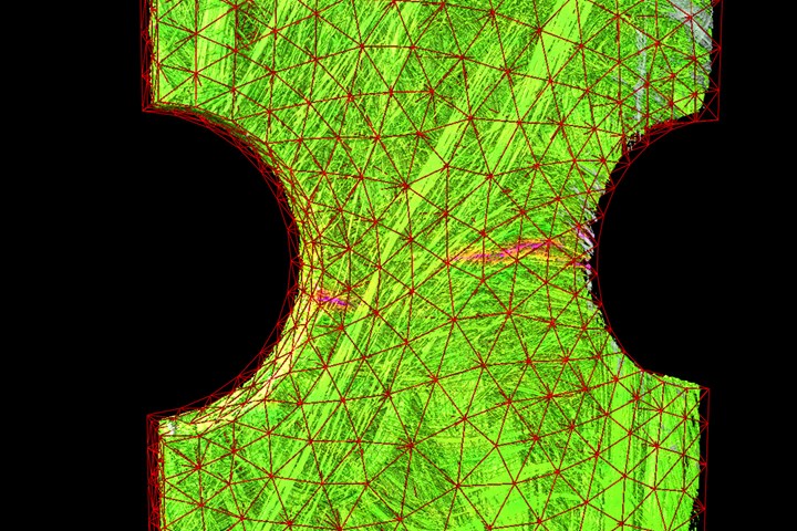
Fig. 1. Strain field of an in-situ test using a novel SMC material. The arising cracks are clearly visible and can be associated with the microstructure characterization, which can be carried out using the same data. All results can be mapped on an FE mesh to easily validate strain fields of FE simulation. Photo Credit: IAM-WK / KIT (Institute for Applied Materials/ Karlsruhe Institute of Technology), Germany.
This is Part 2 of a series on the application of computed tomography (CT) to composite components (see “Applying CT scan data analysis and visualization to composites” for Part 1). Here, I will explore imaging solutions for novel and hybrid composite materials, and provide an example of CT analysis being applied during production.
Novel composites and the trend towards hybrid materials
Hybrid composite materials are the subject of study in both university and industrial R&D settings. While their definition can be traditional in terms of final layup structure, they can be made up of both inorganic nano/micro materials and particulates, and organic substances such as flax, hemp and cotton fibers. As new material combinations present new mechanical behavior, it makes sense to examine their damage behavior for R&D applications.
A technology commonly used to do this is in-situ CT testing, where a material sample or an entire component is strained in a loading stage within a CT-scanner. Here, the material can be loaded and scanned simultaneously, with the resulting data used to evaluate the local displacement and strain tensor, as well as any arising cracks — all in 3D (Fig. 1). But cracks do not necessarily have to be found from in-situ datasets of material samples — it is also possible to compare CT scans of components at different states, such as before and after field tests.
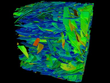
Fig. 2: Flake analysis performed on a composite made of metallic glass within an aluminum matrix. The part was produced using gas pressure infiltration. The color of the structure indicates the orientation of each point and can be used to generate statistics about orientation distribution. Photo Credit: IAM-WK / KIT (Institute for Applied Materials/ Karlsruhe Institute of Technology), Germany.
There are always new composite experiments arising in research institutes where the behavior of an internal microstructure is not well understood, either in the manufacturing process outcome or field performance. Consider, for example, the gas-pressure infiltration of metallic glass with aluminum (Fig. 2). The production of this material via this process is still new, requiring scientists to gain more information about reinforcement distribution and orientation.
Advanced CT-scan analysis can offer deep insight into these challenges by providing data at the prototype and post-test stages. There are many software solutions today that enable users to literally peer inside a material’s fiber/resin structure during all of its lifecycle phases. Below are typical analysis capabilities that can result from this assessment:
- Calculate local fiber orientations and generate statistics such as orientation tensors, or histograms locally or globally per mesh-cell, and linear over-the-material thickness.
- Display local fiber orientation in color code or as vectors or tensors in 3D.
- Detect porosity within a material, either in the matrix or the reinforcement.
- Determine local volume fractions of the reinforcing phase for a variety of composites.
- Measure the cell size and elongation of foams for each cell or use the same analysis to quantify highly filled particle-reinforced composites or powders.
- Calculate displacements and strain fields with digital volume correlation by comparing multiple CT-scans carried out during in-situ tests.
- Compare in-situ datasets at multiple load states for robust crack detection.
- Import FE meshes from any FE software to map microstructure information or strains measured by in-situ testing directly on the mesh.
Industrial applications
Manufacturing costs for composite materials are gradually declining, while production efficiency is increasing. CT offers a means for similarly improving quality assurance across a wide range of industries.
There is no industry more safety-bound than aerospace, which often employs fiber composite material analysis (FCMA) to ensure quality and certification. Many of its applications use unidirectional (UD)-reinforced materials when the loading direction is a certainty. A good example is helicopter rotor blades. Detection of deviation between desired and actual fiber orientation in these blades is critical because the fiber can only support loads in one direction.
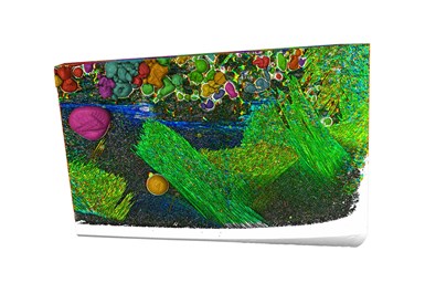
Fig 3. CT-scan analysis software reveals the fiber orientation within a helicopter rotor blade made of lightweight, fiber-reinforced plastic composites (FRP). The Fiber Composite Material Analysis Module for VGSTUDIO MAX enables the processing of both small- and large-scale volume data sets of fiber materials. In small-dimension material samples, the software can show individual fibers. In large-scale volume datasets, larger structures such as fabrics or rovings can be analyzed and visualized. Photo Credit: Volume Graphics
Helicopter blade production is largely characterized by manual work done by highly trained individuals. Every component of such a safety-critical product is checked against specifications for defects such as pores, delaminations or waviness in the fiber deposition. As mentioned, blade stresses are best carried in the longitudinal direction of the fibers. This is where the detailed orientation analysis provided by advanced software comes into play. CT-based analysis can expose deviations in fiber orientation, which can vary blade by blade, allowing results to be easily reviewed by engineers. Until industrial CT came along, the only way to inspect rotor blades was to destroy them. This practice consumed a large number of samples, which is a costly practice.
A bicycle example
Even bicycle development can take on the strenuous attributes of aerospace mission-critical work when composites are involved. Canyon Bicycles started as a small company working out of a garage in Koblenz, Germany, but is now one of the world's leading manufacturers of racing and mountain bikes, e-bikes, as well as triathlon, fitness, urban and kids' bikes. A direct-to-customer company, Canyon is widely recognized for technology innovation, quality, service and design.
Part of Canyon Bicycles’ formula is its rigorous scope of serial testing. All "safety-relevant" components are 100% pre-tested at the production site using X-rays and scan-data analysis. Safety-relevant parts include handlebars for road or mountain bikes, as well as cockpits and rigid forks that are made of continuous carbon-fiber-reinforced polymer. The carbon-fiber composite frames themselves are checked by random sampling against a statistically known catalog of manufacturing deviations that can potentially arise. Prior R&D, field-behavior checks and production testing have quantified the performance and reliability of these parts and streamlined post-production inspection.
A second inspection step for the company is a test that takes place at their main manufacturing site. Here, certain stages of production will once again be X-rayed and software tested. Only then are the bikes assembled.
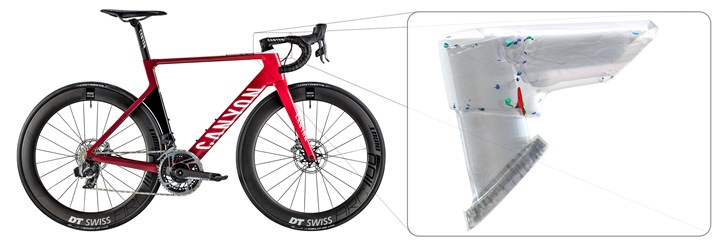
Fig. 4. Insert shows a prototype of a bicycle handlebar stem. Delamination or porosity within the adhesive at the interface between fork shaft and handlebar stem are clearly visible. Such flaws are detected in an early state of design and can be resolved before the part goes to serial production. Photo Credit: Canyon Bicycles
The business metrics from such testing routines are impressive. Canyon Bicycles started composites production almost 10 years ago with a scrap rate of about 20%. By introducing X-ray and CT-scan and data analysis inspection, the company has reduced their scrap rate to less than 1%. Furthermore, quality-assurance testing with CT significantly benefits development. Target-performance comparisons of prototype and CAD model are carried out. For example, in comparing actual performance against digital design, prototypes can be “cut” virtually, providing a view into the component without having to destroy the part. Product quality is high enough to offer customers a six-year warranty on frames, Canyon-engineered parts and road, triathlon and commuter forks.
Inline inspection — when to implement?
Much of the CT scanning and data analysis for composite products is still confined to the R&D stage, where lab work is studied and then tested against manufacturing outcomes. A great deal of knowledge is captured here that, with final field-collaboration testing, can lead to safe assumptions about the behavior of many types of parts.
But this abbreviated practice does not take into consideration the potential total-cost savings of a more rigorous approach to inspection. In the case of Canyon Bicycles, the use of CT scanning, analysis and visualization resulted in a huge improvement in production yield, corresponding labor reduction across product development, higher customer satisfaction, better risk management and strong, performance-based brand identity. Other manufacturing processes could also benefit from such advanced inspection technology, including microscopy and coordinate-measuring technologies.
Application of CT analysis during production is on the rise, from mainstream materials such as metals to the most multi-faceted composites. It is becoming imperative for all mission-critical composite parts to get as close to inline series inspection as possible. Each use-case is different, of course, as with helicopter blades. Automation of both software analysis and production inspection are making advanced CT scanning and data review more and more feasible for competitive, high-performance composite-part manufacturers.
About the Author
Pascal Pinter
(Dr.-Ing.) Pascal Pinter is the product manager for Material Research and Development at Volume Graphics GmbH in Heidelberg, Germany. He holds a Ph.D. in material science from the Karlsruhe Institute of Technology. At the institute for Applied Materials he was employed as deputy head of the hybrid and lightweight materials section and worked on the development of CT evaluation methods. He has a Master of Science in mechanical engineering with a focus on design and robotics and a Bachelor of Science in mechanical engineering with a focus on material science. He has also completed an apprenticeship as a tool mechanic for molding tools.
Related Content
How AI is improving composites operations and factory sustainability
Workforce pain points and various logistical challenges are putting operations resilience and flexibility to the test, but Industry 4.0 advancements could be the key to composites manufacturers’ transformation.
Read MoreAerotech Academy Puglia is inaugurated at Leonardo Aerospace site in Grottaglie, Italy
Joining the Leonardo MaTeRIA Lab and Joint Lab with Syensqo, this aerostructures training course will be 75% materials science and structural design/analysis, 25% digital transformation and AI.
Read MoreToray announces growth, investment in carbon fiber composite materials
As part of its 2023-2025 management strategy, Toray projects 42% growth for pressure vessels, 30% growth in carbon fiber composite materials revenue and a doubling of capital investment.
Read MoreModular, robotic cells enable high-rate RTM using any material format
Airborne’s automated ply placement systems at Airbus, GKN Aerospace and Teijin Automotive Technologies aim to maximize flexibility and intelligent automation.
Read MoreRead Next
Applying CT scan data analysis and visualization to composites
Imaging and analysis via computed tomography (CT) has potential for certifiable safety and business sustainability and could be key for interior inspections of composite parts. Part 1 of a two-part series.
Read MoreAll-recycled, needle-punched nonwoven CFRP slashes carbon footprint of Formula 2 seat
Dallara and Tenowo collaborate to produce a race-ready Formula 2 seat using recycled carbon fiber, reducing CO2 emissions by 97.5% compared to virgin materials.
Read MorePlant tour: Daher Shap’in TechCenter and composites production plant, Saint-Aignan-de-Grandlieu, France
Co-located R&D and production advance OOA thermosets, thermoplastics, welding, recycling and digital technologies for faster processing and certification of lighter, more sustainable composites.
Read More

