
Reinforced thermoplastics in aircraft primary structure
Carbon/PEKK floor beams prove production worthiness of lower cost, fast coconsolidation process.


Design Results:
- Knowledge-based engineering (KBE) tool reduces part design cycle time by more than 90 percent.
- Complex parts with multiple subcomponents can be produced quickly and efficiently by melting or coconsolidating the thermoplastic material.
- A straightforward and tested butt joint design eliminates complicated flange layup, greatly simplifying part production.
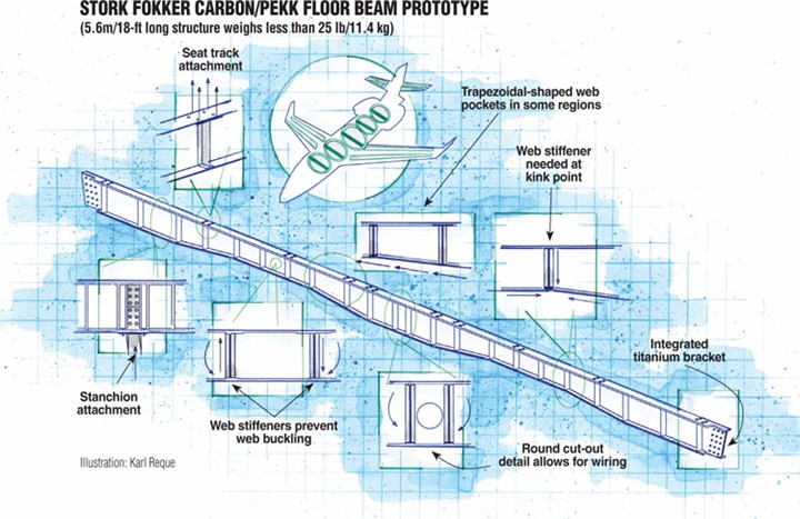
Stork Fokker Carbon/PEKK Floor Beam Prototype Illustration: Karl Reque
Although reinforced engineering thermoplastics have lagged behind thermosets in aircraft structures, they offer compelling design advantages: low weight, inherent toughness and elongation, high service temperature (depending on the matrix) and good fire/smoke/toxicity performance. Thermoplastics also process faster and, unlike thermoset prepregs, store at room temperature. Already a successful proponent of aircraft thermoplastics (see “Thermoplastic composites gain leading edge on the A380,” under "Editor's Picks," at top right), Stork Fokker AESP, B.V. (Hoogeveen, The Netherlands), research partner the Dutch Aerospace Laboratory (NLR) and several material suppliers have for years explored these attributes in primary structure, using optimized material forms and automated processing. While the parts developed to date are demonstrators, Arnt Offringa, Stork Fokker director of R&D, says there is “strong interest” in the concept from more than one aircraft manufacturer.
Setting the bar high
“Our idea was to show how reinforced thermoplastic material could be cost-effectively used in typical structural parts on an aircraft, using innovative designs, joining, coconsolidation and welding,” explains Offringa. The team decided to produce a 5.6m/18.4-ft long, 0.2m/8-inch high floor beam, a complex part produced in large num-bers for commercial aircraft. Because they span the width of a fuselage, these slender members are subject to buckling and must have high strength- and stiffness-to-weight ratios to support passenger and cargo loads.


According to Offringa, an I-shape was selected because it does not have to resist rotation when loaded and thus is the lightest option, compared to other configurations (e.g., Z- or C-beams). It was not, however, the simplest option: “You have to take into account how the beam will be attached to the fuselage, how and where to incorporate stiffeners, how to support passenger seat track pull-off loads in simulated crash cases and the fact that each beam is slightly different in shape and cross-section to accommodate the aircraft’s infrastructure,” notes Offringa.
Joost List, chief engineer at Stork Fokker, explains that a “post-buckling” design was undertaken — that is, under axial compression, even if a beam does buckle, the design has sufficient load-carrying capacity to survive up to ultimate load. Such designs are efficient because they require less material. But, he adds, the analysis is more difficult. Three buckling modes had to be considered: 1) failure of the entire beam, 2) buckling of the beam web in diagonal tension and 3) buckling of the flanges. To achieve geometric stability with minimum amount of material, 28 vertical stiffeners were incorporated (see drawing at right) to create, in effect, smaller “beams within the beam” that resist web buckling. Other design features of the prototype beam included integrated titanium end brackets for connecting the beam to the fuselage frames; round cut-out details to accommodate wiring; kinks in the lower flange to fit around space restrictions: and attachment locations for bolted stanchions (additional support struts) at highly loaded points.
Shortening lead time
“With all of the complexity,” says Offringa, “we needed to shorten the design cycle and allow a designer to vary a large number of beam configurations very simply, even late in the development cycle.” To that end, Stork Fokker developed an in-house iterative stress and design process that enables rapid determination of a beam’s shape, size and layup, based on its position within the aircraft. Beam geometry and ply layup were input along the beam length, together with loads; the in-house software then determined, through stress optimization, the minimum part thickness that would satisfy the load case. After the optimal ply layup was determined along the beam’s length — a process that requires several iterations — the results were fed into Dassault Systémes’ (Paris, France) CATIA V.5 KBE tool, which created the solid models of the beams and the layup tools, in addition to actual shop floor control documents.
Says List, “At one point during the design study, the stress KBE tool enabled us to develop the individual analysis and sizing for all 50 floor beams for an airplane over a weekend. Traditionally, this would have taken several months to complete.”
Starting and restarting
Initial work was done with a carbon/polyphenylene sulfide (PPS) woven fabric semipreg, with the majority of the fibers oriented in the 0° direction. Prototype development began with short beams, in 0.5m/20-inch sections, which were tested with an R/D Tech Omniscan phased-array ultrasonic nondestructive evaluation (NDE) system supplied by Olympus NDT (Waltham, Mass.). Offringa adds that the long, slender beam parts are well suited for inspection using this NDE method, which is qualified with both Boeing and Airbus. Assuming success, 1m/3.3-ft beams would be built and mechanically tested, followed by full-sized beams.
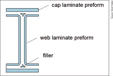
This diagram shows the basic initial floor beam construction, with flanged web, flat cap laminates and fillet or noodle at the cap/web intersection.
Photo Credit: Stork Fokker
Unfortunately, the results with the semipregged fabric were mixed. Although it could be formed into a simple I-beam in the initial 0.5m/20 inch format, when the design was tried in a 1m/3.3 ft section, says Offringa, “we discovered that the woven fabric didn’t work well with the addition of the stiffeners and other complex features.” Additionally, the material proved incompatible with the crucial metal tooling concept: It was designed to fully enclose the part but allow for slight movement of the tooling halves relative to each other, yet still apply even pressure to coconsolidate the different preforms as the thermoplastic matrix melts. “During processing the semipreg’s profile change caused excessive tooling movement,” Offringa explains, “so we couldn’t achieve good consolidation.”
The team then started over, this time with a thinner and (to minimize tool movement) fully impregnated 300-mm/12-inch wide carbon/polyetherketoneketone (PEKK) Cypek unidirectional tape manufactured by Cytec Engineered Materials Inc. (Tempe, Ariz.). Cypek tape processes in a manner similar to PPS, but at a slightly higher melt temperature that is still within the range suitable for high-temperature bagging materials and seals. The tape has a Tg higher than PPS, good toughness and fire/smoke/toxicity properties, while adhering well to other materials, notes Steve Cease, Cytec’s business manager for thermoplastics. It also allowed more precise
tailoring of properties during design, adds Offringa.
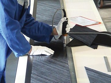
A technician ultrasonically tack welds the web preform for a prototype beam in a layup tool.
Photo Credit: Stork Fokker
To make a prototype beam, preforms were first created using multiple plies of unidirectional Cypek, ultrasonically tack-welded to each other on a specially designed low-pressure preforming press equipped with infrared heating elements. For the web preform, pieces of the uni tape were cut at an angle to create ±45° fibers and joined together by tack welding. Preforms for the flange caps were simply multiple lengths of the uni material. While a balanced laminate was typical, buildups were required at attachment locations. Fillets or noodles were a specially designed pultrusion of carbon/PEKK slit tape, reports Offringa.
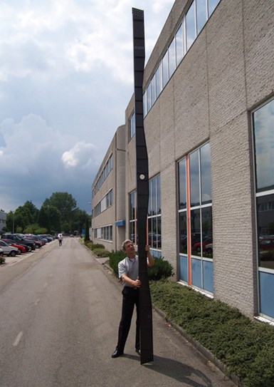
A finished, full-sized 25-lb/11.4 kg prototype floor beam.
Photo Credit: Stork Fokker
The preforms then were brought together in the coconsolidation tool. Initially, the group used a press tool with integrated heating and cooling, but constant pressure over the length of the beam proved difficult to achieve. Eventually, the prototypes were produced using an autoclave — the preform was loaded in the tool and the entire layup then placed in a high-temperature-capable autoclave to achieve the necessary consolidation pressure at the material’s processing temperature of 345°C/654°F. In contrast to thermoset processing times, the autoclave cycle was much shorter, at about two hours.
Mechanical tests (tension and compression) designed to simulate loads applied by cabin seat tracks showed that completed 1m/3.3 ft beam prototype sections easily exceeded aircraft performance requirements. The team then built tooling and a preforming press with integrated infrared heating for the full-length 5.6m/18.4 ft beam. The increased length meant that thermal coefficient of expansion effects were more pronounced than for the shorter beam sections, and tool design had to be improved to ensure consistent leak-free processing. When the tool was optimized, straightness measurements carried out on different beams in two directions confirmed that they were of uniform quality and dimensionally stable. Remarkably, the finished beam weighs less than 25 lb/11.4 kg! Scale-up to full size was achieved in six months.
Improving on success
With a workable carbon/PEKK prototype in hand, the team developed a conceptual plan for two-dimensional, automated pick-and-place preform fabrication with a robot arm that significantly reduced layup time and ensured part reproducibility (Offringa says automated fiber placement or tape laying could also be used) in full production.
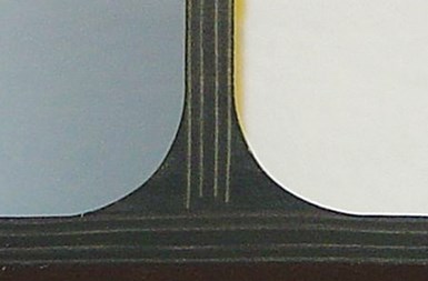
This close-up of a thermoplastic butt joint shows the injection-molded fillet (radius) that supports the joint. The fillet is molded from short carbon fiber-reinforced PEKK granulate.
Photo Credit: Stork Fokker
Meanwhile, the beam design was refined. “The initial vertical ribs were made of two press-formed preforms with flanges, placed back to back, but they ended up being the cost drivers,” says Offringa. “We needed a more cost-effective way to produce them.” The answer was to simplify the web-to-cap connection by eliminating the flanges on the ribs and, instead, simply butt-join flat blades of Cypek material to the beam (see fourth image from top, at right). The butt joint simplified tooling and reduced part tolerance issues because costly, machined recesses, or “steps,” were no longer required to accommodate the flanges. Further, the symmetrical laminate layers that were previously added to the opposite side of the cap to prevent warping were eliminated, saving significant weight. Numerical stress analysis, however, showed that a fillet radius was necessary at the connection between the flat vertical blade and the beam flange. The optimum solution, says Offringa, is a fillet shape that features a molded slot, injection molded from a cost-effective short carbon fiber-reinforced PEKK granulate supplied by Cytec. The slot accept the flat prepreg.
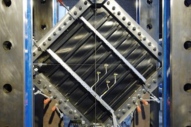
A new flat panel concept with coconsolidated, butt-joined T-stiffeners undergoes testing.
Photo Credit: NLR
The simpler joint relies only on the matrix-to-matrix bond, Offringa points out, but when tested to failure, ”the strength of the butt joint is at least equal to much more complex joints where fibers ‘go around a corner.’”
Two new concepts are in the works: One, a beam design with a sine-wave-shaped web, eliminates the need for vertical stiffeners altogether. The other, a flat panel concept with coconsolidated, butt-joined (matrix-to-matrix) T-stiffeners, is a candidate for fuselage or tail panels and access doors in business jets (see final photo, at right). Tests on panel demonstrators show that very high forces are required to induce failure. Concludes Offringa, “Obviously, our aim is to go into production, and we believe the potential is very high for this type of butt-joint concept to be adopted in real aerospace structure. With reinforced thermoplastics, a designer is free to design complex shapes without incurring high manufacturing costs.”


Related Content

TU Munich develops cuboidal conformable tanks using carbon fiber composites for increased hydrogen storage
Flat tank enabling standard platform for BEV and FCEV uses thermoplastic and thermoset composites, overwrapped skeleton design in pursuit of 25% more H2 storage.
Read More
Developing repairs for thermoplastic composite aerostructures
HyPatchRepair project proves feasibility of automated process chain for welded thermoplastic composite patch repairs.
Read More
Welding is not bonding
Discussion of the issues in our understanding of thermoplastic composite welded structures and certification of the latest materials and welding technologies for future airframes.
Read More
PEEK vs. PEKK vs. PAEK and continuous compression molding
Suppliers of thermoplastics and carbon fiber chime in regarding PEEK vs. PEKK, and now PAEK, as well as in-situ consolidation — the supply chain for thermoplastic tape composites continues to evolve.
Read MoreRead Next

Thermoplastic composites gain leading edge on the A380
Breakthrough manufacturing process produces lightweight, affordable glass-reinforced PPS J-nose on the worlds largest commercial aircraft wing.
Read More
Developing bonded composite repair for ships, offshore units
Bureau Veritas and industry partners issue guidelines and pave the way for certification via StrengthBond Offshore project.
Read More
Plant tour: Daher Shap’in TechCenter and composites production plant, Saint-Aignan-de-Grandlieu, France
Co-located R&D and production advance OOA thermosets, thermoplastics, welding, recycling and digital technologies for faster processing and certification of lighter, more sustainable composites.
Read More