Subsea Wellhead And Pipeline Protection Covers
Wellhead and pipeline protection covers are required under the Norsok regulations for subsea installations in the Norwegian sector (Standard U-002, Subsea Structures and Piping System). Traditional steel wellhead covers are very large — often more than 50 ft/15m square — to allow ROVs access to the Christmas t
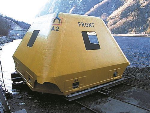
Wellhead and pipeline protection covers are required under the Norsok regulations for subsea installations in the Norwegian sector (Standard U-002, Subsea Structures and Piping System). Traditional steel wellhead covers are very large — often more than 50 ft/15m square — to allow ROVs access to the Christmas tree for maintenance or intervention. At one-quarter the weight of steel covers, the composite versions can be built smaller, allowing the entire cover to be hinged open for ROV access. DML’s Hill estimates total cost savings on the order of 20 percent, compared to steel. Moreover, composites offer the design flexibility to accommodate the varying shapes and sizes of different wellhead types and pipeline configurations.
The Norwegian company Seanor Engineering manufactured the first composite covers in 1992 for Shell Norway. Seanor, later Maritime Seanor, became part of ABB Offshore Systems in 1996, says ABB’s Brevik. “Until recently we were the sole supplier, and we’ve delivered a number of molded composite covers to North Sea operators.”
ABB covers, typically 32.5 ft/10m square and about 23 ft/7m high, are constructed with 0°/90° stitched multi-axial glass reinforcement supplied by DeVold AMT (Langevåg, Norway), Saint-Gobain BTI Inc. (Brunswick, Maine, U.S.A. and Andover, U.K.) and others, and polyester resin from Reichhold Inc. (Research Triangle Park, N.C., U.S.A. and Sandefjord, Norway) and DSM Composite Resins (Zwolle, The Netherlands). According to Brevik, the company hand lays up some of its covers in one piece molds, while even larger versions are typically vacuum infused in two- or four-part molds.
Several plies of material are built up to form the finished solid laminate, which can range in thickness from 1.2 to 2 inches/ 30 to 50 mm. Buildups of material are added at lifting points and at points where brackets are added to support the cover when hinged open. The cover incorporates a composite hinge bar approximately 6 inches/15 cm in diameter, which provides a means of attaching the cover to hinges on the underlying steel base. The steel base has suction or weight anchors for attachment to the sea floor and can also be attached by piling.
The covers are designed to accommodate trawl net loads of 90,000 lbforce/ 400 kN, a trawlboard pull load of 70,000 lb-force/300 kN, and an impact load of 36,875 ft-lbs/50 kJ. “Our approach is to get as much strength as possible from the material, to avoid unneeded buildups,” says Brevik. “We use non-linear finite element analysis to determine the most efficient load paths, and we do a lot of coupon testing to reduce material factors.” ABB has also performed impact testing and several trawl model trials to optimize the cover design. While some seawater will penetrate the laminate, Brevik maintains that it’s not an issue, because the structure is not subjected to fatigue loading.
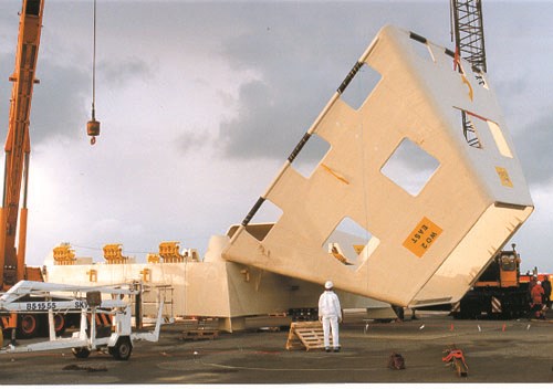
At the 2001 Offshore Europe conference in Aberdeen, a model of the alternative Cocoon was displayed. Designed by Dr. Jerry Baker of Shell U.K. Exploration and Production (Shell Expro) and manufactured by Structural Composite Solutions (Motherwell, U.K.), the cubeshaped Cocoon — approximately 20 ft/6m per side — is made from pultruded fiberglass beams and gratings. Says Structural Composites Solutions’ Malcolm Phillips, “The weight in air of the Cocoon well cover is approximately 5 tons/4.5 tonnes, as compared to 22 tons/20 tonnes, if built of steel.”
The Cocoon’s structure has an internal composite framework made with a pult ruded double-web E-glass and vinyl ester beam. The beam is fabricated with 0° longitudinal rovings, continuous strand mat, 0°/90° fabric and ±45° fabric and has a 55 percent fiber volume. Pultruded Eglass/vinyl ester grating panels are attached to the beams to form the enclosure. According to Phillips, the use of the composite beam and the panels gives the cover structure a high degree of resilience, allowing it to withstand high loads without damage. A field test of the structure was successfully conducted in 100 ft of water at Hunterston Terminal on the Clyde in early 2002. Five Cocoons have been manufactured for deployment in the North Sea.
Related Content
CCG FRP panels rehabilitate historic Northamption Street Bridge
High-strength, composite molded, prefabricated panels solve weight problems for the heavily-trafficked bridge, providing cantilever sidewalks for wider shared use paths.
Read MoreNovel composite technology replaces welded joints in tubular structures
The Tree Composites TC-joint replaces traditional welding in jacket foundations for offshore wind turbine generator applications, advancing the world’s quest for fast, sustainable energy deployment.
Read MoreComposites reinvent infrastructure
Celebrating National Composites Week, CW shares ways in which composites continue to evolve the way we approach infrastructure projects.
Read MoreCSub delivers one-piece composite truss bridge in Norway
EPC supplier has fabricated, transported and delivered a 42-meter composite bridge intended for pedestrians and bicyclists.
Read MoreRead Next
Subsea And Downhole Components
Composite buoyancy elements, riser arch trays, wellhead enclosures and downhole parts meet service challenges.
Read MorePlant tour: Daher Shap’in TechCenter and composites production plant, Saint-Aignan-de-Grandlieu, France
Co-located R&D and production advance OOA thermosets, thermoplastics, welding, recycling and digital technologies for faster processing and certification of lighter, more sustainable composites.
Read MoreAll-recycled, needle-punched nonwoven CFRP slashes carbon footprint of Formula 2 seat
Dallara and Tenowo collaborate to produce a race-ready Formula 2 seat using recycled carbon fiber, reducing CO2 emissions by 97.5% compared to virgin materials.
Read More


