Tailored carbon fiber blanks to move into steel stamping arena
Reduced scrap and cost driving forces behind new technique for automotive industry.
In 1994, Amory Lovins founded the Hypercar Center as a nonprofit through Rocky Mountain Institute (RMI, Snowmass, Colo.) in hopes of developing an ultra-lightweight, super fuel-efficient automobile. Envisioned with an all-composite structure, Hypercar was to have an estimated fuel rating of 100 miles per gallon yet reach 60 mph (96.6 kmh) in about eight seconds. In 1999, however, Hypercar broke away from RMI and became Hypercar Inc., a for-profit organization. In 2003, the company was awarded its first patent on the composite processing technology it intended to use to build the car. That event marked a change in direction and a new name — Fiberforge (Glenwood Springs, Colo.) was born.
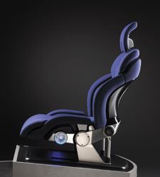
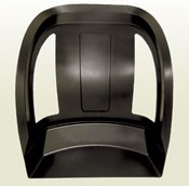
Since then, the company has worked toward commercializing its trademarked Fiberforge "tailored blank" technology, an innovative preforming method, and is targeting the technology at volume manufacturers in military, recreation, commercial, automotive and aircraft markets. After two years of prototyping and development, Fiberforge secured a development contract with Johnson Controls Inc. (JCI, Milwaukee, Wis.) that produced a prototype carbon fiber frame for a car seat. JCI showcased the Genus Concept Seat, made with Fiberforge's seat frame, at the 2005 Detroit Auto show.
The prototype, says David Cramer, VP of engineering at Fiberforge, has brought the company within striking distance of its goal. "Individuals have invested in this technology and companies are evaluating it," he explains, "but we can't yet say when the first volume product will be released."
The idea of a tailored metal blank is not new to the automotive industry, but what sets Fiberforge apart from the field is the use of thermoplastics with continuous, oriented fiber reinforcement. In its effort to develop cost-effective, lightweight structural parts, the company is taking what Jon Fox-Rubin, president and CEO of Fiberforge, calls a 90/10 approach. "We're willing to sacrifice some material performance for increased manufacturing speed," he says. "We endeavor to make parts at 90 percent of the performance of aerospace parts for 10 percent of the cost." Fox-Rubin adds that a major focus is to make the process simple and easy for the manufacturer. CT recently had an opportunity to visit the Fiberforge facility and see the process first hand.
Designing the blank
In a nutshell, a Fiberforge tailored blank consists of multiple plies of thermoplastic prepreg layed down in an automated process, in a predetermined pattern to meet part requirements. The blank is intended for press forming, similar to the process used by automakers to stamp steel blanks. Blank size, shape and thickness are designed using a computer design software program called TailorGen. The software, written by Fiberforge, generates the machine code file (a "G" code-type language) that is used by the Automated Laying System (ALS), the company's self-developed tape-laying machine, to lay up the tailored blank. The software uses a graphical interface and is written in Java, which makes it completely platform independent and, therefore, compatible with Windows, Unix and Apple operating systems.
The software user begins by inputting the desired blank outline using combinations of straight lines, quadratic lines, cubic splines, arcs, ellipses or rectangular sections, or the outline can be input from a DXF file that is generated by the user's standard CAD system. "We do not yet have an automated method to go from the desired part shape to the blank shape," says composites consultant Mike Skinner (Skinner Creative, Draper, Utah), who has assisted Fiberforge in process development. "We use some manual and ad hoc rules of thumb to generate the blank shape," he explains, noting that the company hopes to add an automated feature to the program that will bridge the part/blank gap in the future.
The software recognizes tape width, ply angles and other desired parameters and then calculates the placement of individual prepreg tapes (courses) to completely cover the blank outline at the desired orientations. Users can manipulate individual courses to lengthen or shorten a course or remove courses com-pletely. Users also may add plies at desired angles to build up or strengthen areas of the blank. It reportedly takes about 15 minutes to design a tailored blank with TailorGen, and modifications can be made in seconds during preproduction trials to hone in on the production blank design.
Since the tape-laying system cuts tape courses at 90° angles, the program analyzes part requirements to produce a layup pattern with the most efficient shape and least amount of scrap when, for instance, straight cut tapes must be laid to form a curved part edge.
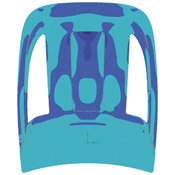
TailorGen also can calculate the thick-ness of the laminate structure, showing the blank thickness in different colors. The program not only generates the pattern, it also keeps a running total of scrap generation. Cramer says the company is investigating ways to add material usage, cost and time analysis to the program so each aspect can be tracked. A sample composite hemispherical part, for example, will have 20 to 30 percent scrap, but the company is looking to bring that down to about 10 percent. Once complete, the pattern information is sent directly to the ALS, which automatically lays up the blank. However, modifications to a blank design still can be made in TailorGen during layup, without stopping the process. Fiberforge also is looking at adapting the program to make it portable, enabling customers to log into the company's Web site, create their own blanks and estimate cost, time, materials and scrap figures.
Laying down the fiber
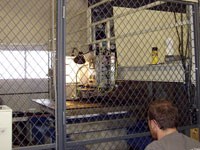
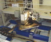
Fiberforge's ALS is much less complicated than typical automated tape placement machines because the head doesn't require multiple axes of motion. A metal table, rather than the head, moves in three axes — x, y and rotational around the z-axis. The layup head, designed and built by Fiberforge, can lay prepreg strips from 35 mm to 75 mm (1.38 inches to 2.95 inches) wide at speeds of up to 1.25 m/sec (49.21 ips). Unidirectional carbon/thermoplastic prepreg tape is measured, layed and cut automatically by the head on the flat, heated "motion table." The prepreg also is heated and partially compacted as it is layed down. "Temperature is critical," says Skinner. "We don't want to mess up the blank with too much heat history [cycles of heating and cooling] that can cause crystallization in some resins."
The current prepreg system of choice is carbon fiber pre-impregnated with nylon resin. "We've used everything from low-grade glass prepreg to aerospace-grade carbon/PEEK material, but we use carbon/nylon as our baseline," Cramer says. The company's thermoplastic prepreg suppliers have included Phoenixx TPC (East Taunton, Mass), Polystrand (Montrose, Colo.), Gurit Composite Technologies (Wattwil, Switzerland) and others.
Tape width and length varies based on the application, Skinner notes, explaining that there is a trade-off between the material and processing speeds: narrow tape is a better choice for blanks with irregular or curved outlines but takes longer to place, while wider tape is faster but yields more scrap. In addition, some tape courses are extended beyond the part boundary far enough to permit the blank to be clamped into a tensioning system prior to the molding step.
Fiberforge currently uses tape reinforced with high-performance aerospace-grade fiber. "We're using material that is over-engineered for this process," Skinner says. In addition, the current tape is fully wet out and consolidated, which, he explains, isn't necessary for their process because it is currently focused on structural parts that do not need to achieve a Class A finish. For that reason, he says, "We could use tape that is around 50 to 75 percent consolidated."
Skinner also contends that use of heavier tow would increase cost-effectiveness. The company has run 24K to 48K tow, but is also testing stretch-broken carbon fiber from Schappe Techniques (Charnoz, France) for applications where increased drape-ability would be desired. (See "Will Stretch-Broken Carbon Fiber Become the New Material of Choice?" under "Editor's Picks," at right.)
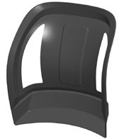
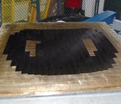
The blank for the Johnson Controls seat back had designed cutouts (spaces where the ALS tape head automatically cuts tapes off and lifts away from the blank at designated intervals, and then drops back down to restart courses). This minimized scrap, leading to a material saving of 7 to 35 percent, says Skinner. Fiberforge used 17 plies of 24K carbon prepreg tape for the seat blank. Plies were laid down at angles of ±45°, 90° and 0°. The blank was partially consolidated by a roller on the tape head, primarily around the edges. Since the blank is press-molded in a secondary process, consolidation of the entire preform isn't necessary, according to the company. The Fiberforge process produces flat blanks, without 3-D curvature or shape, which assume net part shape as a stamping tool compacts the plies.
Stamping shape into the blank
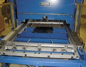
Once a blank is created it then enters the molding process. Currently, the blank is carried by hand to a loading station, where it is manually clamped for tensioning to either a system of tension springs or a slip ring, depending on the finished shape of the part.
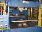
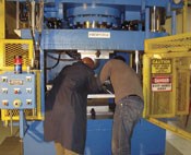
The loading station is integrated into a press designed specifically for Fiberforge by Accudyne Engineering & Equipment Co. (Bell Gardens, Calif.). Clamp locations and the amount of tension placed on the blank are im-portant variables. Tension is not intended to stretch the blank, but instead keeps the blank in position, suspended at the proper distance from the tools as it is heated on both sides.
Cramer explains that figuring out where to place the springs for tensioning the seat back was a bit tricky. "How you hold it is the trick to getting the blank to form properly." Ultimately, 12 springs were placed around the edge of the blank, sometimes with the clamps pulling the edges in opposite directions. When the blank was clamped in, it then was shuttled into the heating unit comprised of 128 infrared heating elements. The number of elements permits engineers to customize the intensity and location of heat needed to uniformly heat the blank to the desired temperature. Typically the blank is heated for about two minutes before it is shuttled into the press. The custom press is designed to close much more rapidly than conventional presses, to prevent the blank from cooling prior to molding.
The blank is pressed between integrally heated upper and lower tools, which are designed to permit rapid tool changeover. The part is pressed for about 1 minute at a pressure much higher than that commonly used in thermoforming. A typical thermoformer usually presses at 120 psi (8.27 bar) but the press used by Fiberforge operates at 800 psi to 1,000 psi (55.6 bar to 68.95 bar). The increase is necessary because the closely packed unidirectional fibers tend to inhibit the flow of resin. Once the part is molded, it is removed from the press and the flash is trimmed, resulting in a finished Genus seat back.
Enhancing the process
Fiberforge is looking at ways to make its technology easier to use and even more affordable. For example, the company is investigating ways to use lower-cost prepreg, semi-impregnated tape and, potentially, tape produced inline during layup. In the case of the latter, continuous carbon fiber and resin could be combined as each is fed into the head of the automated laying system. Additionally, the blanks could be tape layed and then placed on an indexed conveyor by a robotic system, to pass through the preheating chamber and move on to a stamping cell and on, again, to a machining cell for flash removal as well as a final buffing station, where the part would be cleaned.
When fully automated, the Fiberforge system's production capacity is expected to increase considerably, making production at automotive industry rates a reality. Cramer says Fiberforge hopes to be able to produce products from raw resin and fiber soon, but is not yet ready to put a timeline on the system's development.
When all the components of the proposed automated system are up and running, the company will be willing to license the entire technology, or parts of it, to customers, but also is willing to mass produce either blanks or finished parts for customers as well.
"We've got a beta product," says Cramer. "Now we're focused on creating customers for it."
Related Content
SMC composites progress BinC solar electric vehicles
In an interview with one of Aptera’s co-founders, CW sheds light on the inspiration behind the crowd-funded solar electric vehicle, its body in carbon (BinC) and how composite materials are playing a role in its design.
Read MoreCarbon fiber, bionic design achieve peak performance in race-ready production vehicle
Porsche worked with Action Composites to design and manufacture an innovative carbon fiber safety cage option to lightweight one of its series race vehicles, built in a one-shot compression molding process.
Read MoreComposite molding compound replaces Invar for lightweight small satellite structures
Patz Materials and Technologies and Lawrence Livermore National Laboratory developed a new monolithic optics housing with 80% less weight, near-zero CTE and the high-volume manufacturing required for commercial space.
Read MoreManufacturing the MFFD thermoplastic composite fuselage
Demonstrator’s upper, lower shells and assembly prove materials and new processes for lighter, cheaper and more sustainable high-rate future aircraft.
Read MoreRead Next
Plant tour: Daher Shap’in TechCenter and composites production plant, Saint-Aignan-de-Grandlieu, France
Co-located R&D and production advance OOA thermosets, thermoplastics, welding, recycling and digital technologies for faster processing and certification of lighter, more sustainable composites.
Read MoreVIDEO: High-volume processing for fiberglass components
Cannon Ergos, a company specializing in high-ton presses and equipment for composites fabrication and plastics processing, displayed automotive and industrial components at CAMX 2024.
Read More


