Damage tolerance testing of sandwich composites: The sandwich flexure-after-impact (FAI) test
A second new ASTM-standardized test method assesses the damage tolerance of sandwich composites under flexural loading.
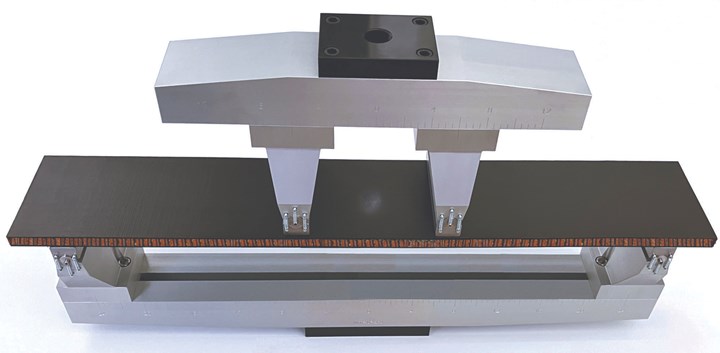
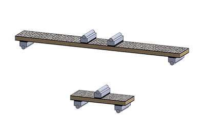
Figure 1. Sandwich flexure-after-impact (FAI) test fixture and specimen. Source (All Images) | Dan Adams
In my January 2024 column, I reported on a new ASTM test method for use in assessing the damage tolerance of sandwich composites under compression loading: the sandwich compression-after-impact (CAI) test, ASTM D82871. A second damage tolerance test for sandwich composites was also recently standardized: the sandwich flexure-after-impact (FAI) test, ASTM D83882. This column focuses on this flexure-loaded damage tolerance test method and provides comparisons to other existing damage tolerance test methods for composites.
Damage tolerance testing of composites refers to the testing of specimens with a centrally located damage site under a specified loading condition. Typically, the damage is produced by drop-weight impacting, which can produce extensive internal damage that is difficult to detect by visual inspection. For composite laminates, damage tolerance testing is commonly performed under in-plane compression loading because their compression strengths are lower than their tension strengths and therefore more critical in many designs. Additionally, impact damage typically has a greater effect on compression strength.
Why two test methods?
The ASTM D71373 test method, initially standardized in 1999, is commonly followed for determining the CAI strength of composite laminates. Note that the sandwich CAI test that was discussed in the January 2024 column is similar to this laminate CAI test method. However, the size of the sandwich CAI specimen has been increased significantly to allow for the larger impact damage areas produced in sandwich composites and to accommodate the use of strain gages for specimen alignment during compression loading.
Perhaps an initial question to address is why it’s necessary to have two damage tolerance test methods for sandwich composites: one for compression loading and one for flexure loading. Compression loading of the impact-damaged facesheet is usually the most critical, and therefore an edgewise compression test in which both facesheets are compression-loaded is of interest. However, sandwich composites are commonly subjected to flexural loading, resulting in both a tension-loaded and compression-loaded facesheet. Although the compression-loaded facesheet usually fails first under flexural loading, the resulting FAI strength often differs from the CAI strength. Therefore, even though failure usually occurs in the compression-loaded facesheet for both loading configurations, two separate test methods are desired. The choice of which sandwich damage tolerance test method to perform may be based on the primary loading of the intended application.
The FAI test
The ASTM D8388 sandwich FAI test was published as a standard practice rather than a standard test method, as it supplements the existing ASTM D72494 long beam flexure test method for use with impact-damaged sandwich composite specimens. The primary modifications specified in the standard practice address the sandwich FAI specimen dimensions as well as the span lengths used in flexural loading. As with the standard long beam flexure test method, the sandwich FAI test (Fig. 1) uses a four-point flexure loading configuration with two outer supports below the specimen and two inner loading heads above the specimen. This loading configuration produces a uniform bending moment and zero shear force across the specimen inner span while minimizing the shear forces in the outer spans.
For sandwich FAI testing, the inner loading span length was increased from 100 millimeters to 150 millimeters to minimize interactions between the impact damage and the inner loading points. Additionally, the outer support span was increased from 560 millimeters to 610 millimeters to further reduce the shear stresses in the sandwich core. This standard loading configuration is intended to maximize the bending stresses in the facesheets while minimizing the shear stresses within the core. However, the sandwich specimen design equations provided in the ASTM D7249 long beam flexure standard should still be used to confirm that facesheet failure will be produced.
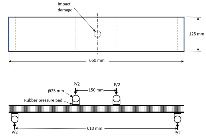
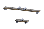
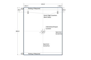
Figure 2. ASTM D8338 sandwich FAI standard specimen configuration. Shown here are overall specimen dimensions (top) and a front view indicating where the fixture contacts the specimen (bottom).
As in the long beam flexure test method, 25-millimeter-wide pivoting loading flats are used to distribute the force over a larger loading area. Additionally, 3-millimeter-thick rubber pressure pads are placed onto the steel flats to avoid localized facesheet damage or core crushing. Note that the impact-damaged facesheet is placed facing upward in the test fixture with the damage centered between the inner loading heads, thus producing compression loading in the damaged facesheet. The only acceptable failure modes are those that occur at the impact damage location in the compression-loaded facesheet. Another option, if desired, is to place the impacted facesheet into the test fixture facing downward, resulting in a flexural-loaded tension-after-impact test.
The sandwich FAI specimen width was also increased — from 76 millimeters to 125 millimeters — to produce a specimen width-to-damage diameter (w/D) ratio of approximately 5:1, the recommended w/D ratio used when impacting sandwich specimens in accordance with ASTM D77665. This increased specimen width is intended to prevent impact damage from extending beyond one half of the specimen width while producing sufficient flexural strength reductions to permit damage tolerance comparisons. Additionally, the sandwich specimen length was increased from 600 millimeters to 660 millimeters. The resulting sandwich FAI specimen dimensions are shown in Fig. 2.
The ASTM D8388 sandwich FAI test was published as a standard practice rather than a standard test method.
It is worth mentioning that because of the dominating presence of the impact damage in the center of the compression-loaded facesheet, the resulting sandwich FAI strengths are relatively insensitive to parameters of concern in the undamaged sandwich long beam flexure test, such as failure at the loading points and rough or uneven specimen edges.
Although quasi-isotropic laminates are typically used for damage tolerance testing of composite laminates, the facesheet ply layup and core configuration for sandwich composite FAI specimens are often selected to represent the intended structural application. Therefore, proper design of the sandwich configuration as well as the FAI loading configuration is required to avoid core crushing or core shear failure. This means that the facesheets must be sufficiently thin and the support span sufficiently long to produce facesheet failure prior to core shear failure. Additionally, the core must be sufficiently thick to avoid excessive deflection during flexure loading. Note that the specimen design equations provided in the ASTM D7249 long beam flexure test method can be used to help arrive at suitable specimen designs for sandwich FAI testing. Additional information on the development of the ASTM D8388 sandwich FAI test method is available in reference 6.
Over the last 2 years, I’ve introduced CW readers to four new standardized test methods for sandwich composites. The first two were new test methods for notch sensitivity testing: a sandwich open-hole compression test and a sandwich open-hole flexure test. The most recent two are for damage tolerance testing: a sandwich CAI test and the current sandwich FAI test. Note that there are also ongoing activities within the CMH-17 Sandwich Disbond Working Group as well as ASTM Committee D30 to develop additional test methods for assessing the fracture toughness of sandwich composites. I’ll keep CW readers informed as these sandwich test methods approach ASTM standardization.
References
1ASTM D8287/D8287M-22, “Compressive Residual Strength Properties of Damaged Sandwich Composite Panels,” ASTM International (W. Conshohocken, PA, US), 2022.
2ASTM D8388/D8388M-22, “Standard Practice for Flexural Residual Strength Testing of Damaged Sandwich Constructions,” ASTM International (W. Conshohocken, PA, U.S.), 2022.
3ASTM D7137/D7137M-23, “Compressive Residual Strength Properties of Damaged Polymer Matrix Composite Plates,” ASTM International (W. Conshohocken, PA, US), 2023 (first issued in 1999).
4ASTM D7249/D7249M-20, “Facesheet Properties of Sandwich Constructions by Long Beam Flexure,” ASTM International (W. Conshohocken, PA, U.S.), 2020 (first issued in 2006).
5ASTM D7766/D7766M-23, “Standard Practice for Damage Resistance Testing of Sandwich Constructions,” ASTM International (W. Conshohocken, PA, US), 2023 (first issued in 2011).
6Kuramoto, B.K, Stanfield, M.L., and Adams, D.O., “Development and Evaluation of the Sandwich Flexure After Impact Test,” to appear in the Journal of Sandwich Structures and Materials, 2024.
Related Content
Measuring ply-wise deformation during consolidation using embedded sensors
Strip-type shape sensor method claims real-time measurement of ply-wise deformation.
Read MorePhotothermal tomography for locating, quantifying defects in composites
Years of infrared testing development result in thermography technology that is no longer just qualitative, but can define defect size and depth, making additional UT scans obsolete.
Read MoreTesting to support composite bolted joint analysis
An overview of ASTM Standard Guide D8509, and its coupon-level mechanical testing of design properties for analyzing composite bolted joints.
Read MoreDamage tolerance testing of sandwich composites: The sandwich CAI test
A new ASTM-standardized test method established in 2022 assesses the compression-loaded damage tolerance of sandwich composites.
Read MoreRead Next
Flexure testing of sandwich composites
Dan Adams assesses the facesheet or core failures for three-point and four-points flexural loading configurations.
Read MoreComposites testing as part of a building block approach, Part 1: Coupon-level testing
The building block materials testing approach is a step-by-step process that serves as a framework for designing composite structures while also reducing risk and cost.
Read MoreDesigning and manufacturing turbine test nacelles
Michigan-based Ground Test Solutions (GTS) shares the design and manufacturing processes involved in building composite nacelle components used in testing jet and helicopter engines.
Read More

