NASA worked with Aurora Flight Sciences and the University of Michigan to design, optimize and fabricate this 39-foot subscale wing to assess the performance of steered carbon fiber tows in wing skins. The project, called Passive Aeroelastic Tailoring (PAT), aimed to evaluate M&P technologies to enhance aeroelastic and aerodynamic behavior and decrease wing weight and fuel burn in next-generation aircraft. The wing is shown here in a test stand at NASA’s Armstrong Flight Research Center. Photo Credit: NASA
Up to now, the use of tow steering in automated fiber placement (AFP) has been implemented carefully and selectively, and mainly in an effort to accommodate relatively modest contours in tool and part designs that demand tow placement flexibility, particularly in large aerostructures.
As CW reported in Part 1 of this two-part series, published in the December 2020 issue, although some AFP suppliers have demonstrated the ability to place tows at radii as small as 11 inches (280 millimeters), in a production environment radii typically range from 1.0 to 1.5 meters. And even then, such steering usually sees limited use, particularly given the fact that composite aerostructures operate in a certification environment that favors traditional quasi-isotropic ply schedules.
Thinking about the future, however, it’s not too difficult to imagine creative ways tow steering might be deployed to design and build aerospace parts comprised of super-optimized, highly steered composite structures that are decoupled from the highly regimented, quasi-isotropic world in which aerocomposites currently live. And it’s not too difficult to understand that an aircraft wing skin might be the ideal candidate for such a technology. The Boeing 787 and the Airbus A350, which feature commercial aviation’s first all-composite wings, helped aircraft designers realize a step change in aerodynamic performance. What might the next step be in wing design and engineering, and how might tow steering enable that?
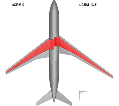
Fig. 1. The NASA PAT project first optimized tow steering for two wing models. The first, uCRM-9, has an aspect ratio of 9.0 and is typical for commercial aircraft flying today. The second, uCRM-13.5, has an aspect ratio of 13.5 and is longer and thinner than the uCRM-9 model. High aspect ratio wings are considered necessary to increase fuel efficiency in next-generation aircraft. Photo Credit: University of Michigan
Passive Aeroelastic Tailoring
The most thorough evaluation conducted yet on the feasibility of using tow-steered composite structures in an aircraft wing was performed in a project led by NASA and involving Aurora Flight Sciences (Manassas, Va., U.S.), the University of Michigan (Ann Arbor, Mich., U.S.) and the Georgia Institute of Technology (Atlanta, Ga., U.S.). The project, called Passive Aeroelastic Tailoring (PAT), is part of NASA’s Advanced Air Transport Technology (AATT) project and was organized to design and assess the use of passive aeroelastic tailoring on a high aspect ratio wing. PAT launched in 2014 and issued its final report in February 2020.
Karen Taminger, senior materials research engineer at NASA Langley (Hampton, Va., U.S.) and project technical lead for PAT, says the goal of the research was to look two to three generations into the future of aircraft wing manufacturing to find a path that enabled 50-60% fuel burn reduction. “What technology will be needed to dramatically reduce fuel burn and emissions?” she asks. “And how can a higher aspect ratio wing — longer, thinner, more aerodynamic — make that possible?”
Taminger notes that the current aspect ratio (the ratio of the span to the mean chord of a wing) of a commercial aircraft wing is approximately 9.0. The PAT project contemplated increasing that ratio by 50% to 13.5 by increasing wing length and reducing the mean chord. “The problem is that when you do that, the wing becomes more flexible and ‘floppy,’” Taminger notes. “We wanted to use tow steering to control the wing’s tendency to flutter.” Doing so would involve the use of tow steering in the wing skins to bias the wing structure and control wing tip behavior. Taminger says the leading edge of a wing, particularly near the wing tips, tends to rotate up and out when under load, which harms the aeroelastic efficiency of the craft. A more efficient aeroelastic structure, she says, would “wash out” under load and bias the wing to rotate the leading edge near the tip forward and down — using a structural attribute called bend-twist coupling. Further, it would do all of this without mechanical actuation.
The PAT project was divided into four phases. In the first, representative test panels were fabricated to demonstrate the feasibility of using steered tow paths with conventional AFP systems. These panels were then used for mechanical coupon testing to characterize the strength differences between steered and unsteered laminates. The second phase was performed by the University of Michigan’s Multidisciplinary Design Optimization Laboratory, a graduate research group lead by professor Joaquim R. R. A. Martins. This phase focused on optimization of a high aspect ratio, tow-steered wing, with assessment of potential fuel burn savings, weight savings and aeroelastic performance. In the third phase, performed by Aurora Flight Sciences, a 27% (39-foot/12-meter) scale wing structure was fabricated using tow steering patterns developed during the optimization phase. In the fourth and final phase, NASA subjected the subscale wing to structural testing at the Armstrong Flight Research Center’s (Edwards Air Force Base, Calif., U.S.) Flight Loads Laboratory to correlate predictions from the optimization phase with the physical product.

Fig. 2. Tow steering for the PAT project focused on four patterns in order to simplify design and optimization. Because tow steering allows for deviation from traditional quasi-isotropic layups, each pattern is based on a reference tow orientation field (θ0). This reference orientation field gives the local tow direction for the first tow pattern, referred to as the main tow pattern. The remaining three tow patterns are then defined by offsetting the main tow orientation by 45°, −45° and 90°. Photo Credit: University of Michigan
Design optimization
The design optimization work done by the University of Michigan laboratory was led by Tim Brooks, who was a graduate student at the time in the Department of Aerospace Engineering, researching the application of tow steering in aerostructures. A summary of his work can be found in a paper he wrote with Martins and Graeme J. Kennedy, an assistant professor in the School of Aerospace Engineering at the Georgia Institute of Technology. Their paper, titled “High-fidelity Aerostructural Optimization of Tow-steered Composite Wings,” was published in February 2019 in the Journal of Fluids and Structures. “We wanted to take advantage of the directional stiffness offered by steered tows,” says Brooks, who has since graduated from the University of Michigan. “We wanted to come as close as possible to isotropic properties in a composite wing skin in a larger, more efficient wing.”
Brooks et al. note in their paper that current aerostructures tend not to take full advantage of the benefits provided by tow steering. “One reason for this is the difficulty in defining certification standards for these unconventional laminates,” they say. “The second reason is that there is only limited work quantifying the benefits of adding tow steering into the composite design of complex structural components, such as the wing structure. Another challenge in the design of tow-steered structures is that it is not obvious nor intuitive what the tow paths should be for such a structure so that it maximizes the benefits offered by its variable directional stiffness properties. The goal of the present work is to address the latter two difficulties by developing a methodology for performing high-fidelity multidisciplinary design optimization (MDO) of tow-steered structures, and quantifying the benefits of tow steering for flexible wing design.”
The modeling Brooks et al. did focused on the use of tow steering in two wing models, each of which is based on the undeflected Common Research Model (uCRM). The uCRM is, in turn, based on the aerodynamic benchmark wing design called the NASA Common Research Model (CRM). The first uCRM variant, uCRM-9 (9.0 aspect ratio), maintains the original wing planform of the CRM with dimensions and structures similar to that found on a Boeing 777 aircraft. The second variant, uCRM-13.5 (13.5 aspect ratio), is modified to be longer and thinner to achieve the higher aspect ratio (Fig. 1). All of the optimization work focused on application of tow steering in wing skins only, not in stringers, spars or ribs.
Brooks says one of the early challenges of the structural modeling stemmed from the fact that the use of tow steering allows, in theory, a unique tow pattern for each layer of the laminate, and in a thick laminate like a wing skin, that’s a lot of unique tow patterns. In the paper, Brooks et al. note that “since the number of iterations required to converge the optimization scales with the number of design parameters, this increase in design parameters may result in prohibitively expensive optimization problems.”
To avoid this optimization hurdle, Brooks et al. decided to restrict each layer of the wing skin laminate to one of four tow patterns. However, the use of tow steering obviates the standard directionality (0°/90°/±45°) employed in AFP. Because of this, Brooks et al. defined a reference tow orientation field (θ0). “This reference orientation field gives the local tow direction for the first tow pattern, referred to as the main tow pattern,” the paper says. “The remaining three tow patterns are then defined by offsetting the main tow orientation by 45°, −45° and 90°, such that the resulting laminate remains locally orthotropic with respect to the main tow path.” In addition, the reference axis for all ply angles in the skins is defined to be parallel to the leading edge of the wing (Fig. 2).
Brooks says the minimum tow radius chosen for the design optimization calculations was 70 inches (1.8 meters) using 0.25-inch carbon fiber tows. This is on par with radii currently in use in aerospace manufacturing. The goal, Brooks reiterates, was not to push the limits of tow steering radii, but to develop design optimization criteria for the application of steered tows in a wing skin, and for how such optimization translates into a lighter, stronger, more efficient aerostructure.
The Brooks paper details the calculations performed during the optimization project, including predictions of lift, twist, bend-twist and other performance parameters. The optimization calculated maneuver load limits from -1.0G up to 2.5G. The authors also calculated wing mass and fuel burn savings, as well as maximum takeoff weight (MTOW) advantages to be realized using tow-steered skins. Brooks and his team also allowed the optimizer for the uCRM-9 model to rotate or offset the layup of each skin with respect to the wing’s leading edge to increase aeroelastic efficiency. Such a “conventional rotated” design would, in theory, be more efficient than a conventionally designed and manufactured structure, but less efficient than a tow-steered structure. Table 1 shows the results of the calculations from the optimization studies.
Table 1. Summary of wing design optimization studies
|
Design model |
Parameter |
Tow-steered plies |
Conventional tow plies |
Conventional rotated plies |
|
uCRM-9 |
Fuel burn (kg) |
85,535 |
87,558 |
86,745 |
|
MTOW (kg) |
262,937 |
269,575 |
266,831 |
|
|
Wing mass (kg) |
14,402 |
19,016 |
17,086 |
|
|
uCRM-13.5 |
Fuel burn (kg) |
75,918 |
77,062 |
N/A |
|
MTOW (kg) |
255,960 |
259,857 |
N/A |
|
|
Wing mass (kg) |
17,042 |
19,796 |
N/A |
The data from the work of Brooks et al. shows that a wing fabricated with a skin optimized using steered tows does in fact provide the bend-twist coupling desired to achieve washout conditions, and provides fuel burn and MTOW advantages. The mass of the uCRM-13.5 wing versus the standard uCRM-9 is greater, but this is due in large part to the fact that the uCRM-13.5 wing is a larger structure. The next step in the PAT project was to take the design data from Brooks’ calculations and apply them in the fabrication of a wing structure.
Tow-steering in action
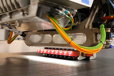
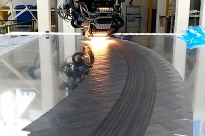
As noted already, fabrication of the subscale (39-foot) wing structure was performed by Aurora Flight Sciences (AFS). The wing, based on the uCRM-13.5 finite element model (FEM), included an upper and lower skin, a leading edge spar, a trailing edge spar and 58 ribs. The wing was manufactured in Columbus, Miss., U.S., using an Electroimpact (Mukilteo, Wash., U.S.) gantry-based AFP system equipped with an eight-tow head. Park Aerospace (Newton, Kan., U.S.) supplied the carbon fiber prepreg material, which comprised 0.25-inch-wide tows of the company’s 130-gsm HTS45/E-752-LT material.
Much of the AFS work was headed up by Clint Church, VP of engineering at AFS, who could not be reached for this report. However, working with Church was Ben Smith, who has since left AFS and is currently chief engineer at Resonant Sciences (Dayton, Ohio, U.S.). Smith says that Brooks's incorporation of manufacturing constraints within the optimization was invaluable in achieving a manufacturable design. “It made that detailed design-to-manufacturing process really smooth,” Smith says.
AFS followed the design parameters defined by the optimization, applying one of the four unique tow patterns established by Brooks et al. Again, these patterns relied on the use of a tow orientation field (θ0) that provided a reference point for the tow patterns that followed. Fig. 2 shows the four tow patterns employed and their theoretical ply fraction percentage.
Fabrication of the subscale wing structure, however, varied slightly from these ply fractions as the optimized thickness (based on a continuous variable) was rounded up to whole plies. Skin laminates were designed with repeating units of [0°, 0°, 90°, 0°, 0°, 45°, 0°, -45°]s, with ply drops taken from the center of the laminate and selected such that the desired ply fraction was maintained. For the upper wing skin, thickness ranged from 96 plies (0.505 inches) at the root, to 104 plies (0.546 inches) at the Yehudi break (the second kink in the trailing edge spar), to 44 plies (0.24 inches) at the tip. For the lower wing skin, thickness ranged from 76 plies (0.395 inches) near the root to 14 plies (0.087 inches) near the tip.
The upper skin actual ply fraction for 0° plies ranged from 61.7-64.0%; 90° plies from 12.0-13.8%; 45° plies from 11.4- 13.3%; and -45° plies from 10.9-12.8%. The lower skin actual ply fraction for 0° plies ranged from 60.0-66.7%; 90° plies from 11.1-15.8%; 45° plies from 10.0-14.3%; and -45° plies from 7.1-13.3%.
A particular concern in the application of tow steering is the development of tow-drop criteria for tow convergence zones. When tows are steered, tow courses rarely meet edge-to-edge as they do in a non-steered design. As a result, gaps and overlaps are created where tows converge or diverge at off angles, thus creating convergence zones, which can have deleterious knockdown effects on skin performance (Fig. 3). Smith says tow drops were scheduled according to an overlap percentage criteria. For example, Smith says, if an overlap exceeded 50% of the width of a tow, one tow would be dropped from the course. Conversely, if a gap exceeded 50% of the width of a tow, one tow would be added to the course.
Another challenge inherent to tow steering is tow buckling along the inner edge of the radius. As noted in Part I of this report, the tendency of a tow to buckle depends on a variety of factors, including tow thickness, tow stiffness, resin type, fiber type, tow radius, arc length, compaction technique, compaction time, AFP heat source type and more. Regardless of cause, buckling can be ameliorated with debulks, or by the application of subsequent plies, but an accumulation of buckling in a region can adversely and possibly prohibitively affect mechanical properties.
It should be noted that the infrared heating technology employed in the Electroimpact AFP used in the PAT subscale wing fabrication is not considered, according to Electroimpact, current state-of-the-art technology for tow steering. The company noted, in Part I of this report, that its current systems rely on laser (not infrared) heating of the substrate and the tows, as well as independent compaction for each tow being placed. Both of these advancements have been proven to increase the quality and reduce the radius of tow steering.
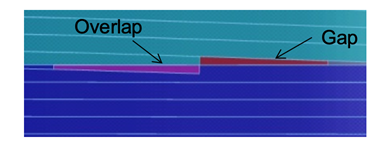
Fig. 3. One of the challenges inherent to tow steering are convergence zones, where tows intersect at off angles. The result is a series of overlaps and gaps that must be carefully managed. For the NASA PAT project, criteria were developed that determined when tows should be dropped or added, depending on the width of the overlap or the gap. Photo Credit: NASA
Testing, correlation, new questions
The PAT program subsequently subjected the subscale, tow-steered wing that AFS fabricated to a series of static load and ground vibration tests (Fig. 4). This was done to assess the efficacy of tow steering in general, the bend and twist behavior tow-steering engenders, the mechanical performance of the spars and ribs and the correlation of real-world performance to predicted performance as established by the optimization program run by the University of Michigan.
The final report of the PAT program issued by NASA outlines in great detail results from all of the testing. NASA’s Taminger notes that the subscale wing, thanks to the application of steered tows, did exhibit the “bend and twist” behavior desired in the tip. Further, NASA’s final report says that “most data correlate very strongly with predicted models.” The exception was a discrepancy in the tip deflection. This is attributed to two sources: The first, and largest, is the “rigid body rotation,” which was not properly accounted for in the model. The second source is associated with fastener joint stiffness, which produced more compliant joints and, thus, larger tip deflections than modeled. The report also suggests that further work is required to mitigate flutter.
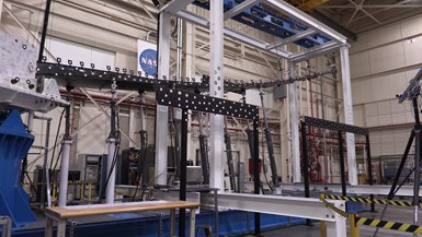
Fig. 4. The 39-foot PAT wing, with steered tow skins, was subjected to static load and ground vibration testing by NASA at the Armstrong Flight Technology Center. The goal of the testing was to assess strength and aeroelastic characteristics of the wing, and to correlate test data to optimization data. Results showed generally strong correlation, encouraging aeroelastic behavior. Photo Credit: NASA
A project like PAT, by design and necessity, tends to create as many questions as it answers about if and how tow steering might be applied in aerostructures. The NASA report, for its part, suggests, “Compounding benefits may be obtained by combining tow steering technologies with other wing technologies, such as active load alleviation. By coupling both technologies in a single optimization, an accurate assessment of the combined performance, limitations and relative benefits can be obtained.”
The report also recommends application of tow steering in any aerostructure in which principal load direction changes may benefit by maintaining alignment with the load direction. Such structures include spars and fuselages. The report’s final comment is possibly the most important: It notes that the prevalence of overlaps, gaps and fiber buckling demand either more M&P work to mitigate their knockdown effects, or a more robust testing and certification regime that predicts their occurrence and effects. “Because the tow steering process so significantly opens the design space, it is anticipated that traditional composite material testing matrices will quickly become intractable,” the report says. “Therefore, advancements in the analysis and cost-effective testing must be developed prior to certification.”
The challenge of qualifying and certifying structures optimized with tow steering is a serious one. Brooks notes that “no one has experience trying to characterize or certify a tow-steered structure. The laminate has no fixed characteristic — the location determines the fiber angle. Is it possible to fabricate a coupon for each possible variation? It’s just not feasible.” Brooks also says designing and fabricating a tow-steered structure takes disproportionately more time than a conventional layup. “There is a learning curve here,” he says. “Something would have to be improved upon to meet rateand scale requirements.”
Smith argues that evolution to a fully tow-steered aerostructure could be done incrementally and suggests a hybrid structure as a good intermediate step. Under this design strategy, an aerostructure could combine ply regions of conventional steering (called “low aggressiveness”), where mechanical loads are less demanding, with regions of “high aggressiveness” where tow steering is deployed to meet higher mechanical loads. “There are trade-offs that come with tow steering,” he says. “Where does the knockdown [of tow steering] outweigh the performance benefit, and where does the performance benefit outweigh the knockdown? Tim’s [Brooks] work could be used to explore this idea.”
Another intermediate and more manageable application of tow steering in aerostructures, pointed to by Brooks, Smith and the NASA report, would be in aircraft door, window and panel surrounds. Such structures would benefit greatly from tow steering and could be more readily designed and modeled.
Taminger, commenting on certification, notes that one of the PAT project’s goals was to “explore the possibilities and show what can be done. We steered clear of certification initially because we thought it was important to first prove the benefit of the technology.” That said, she acknowledges that the integration of traditional quasi-isotropic composite structures into the PAT program was done to “give us a connection to something that is certified and has been flying.” Still, there is an order-of-magnitude increase in complexity when an aerostructure is designed to apply tow steering the way the PAT project did, and traditional testing and certification tools are not equipped to manage that complexity. A technology such as tow steering, Taminger suggests, might help accelerate the development and application of “certification by analysis,” which NASA is also evaluating in a separate project.
It is clear that tow steering in aerostructures has a future that might be guided, in part, by the work done on the PAT project. It was a project that seemed, to Taminger, highly audacious as it began. “When we started,” she says, “the idea at the heart of this project sounded good. Along the way it changed the way we think about designing and manufacturing wings. To go from idea to proof that we could build a wing much better than we thought we could was a real eye-opener.”
Related Content
Improving carbon fiber SMC simulation for aerospace parts
Simutence and Engenuity demonstrate a virtual process chain enabling evaluation of process-induced fiber orientations for improved structural simulation and failure load prediction of a composite wing rib.
Read MoreASCEND program update: Designing next-gen, high-rate auto and aerospace composites
GKN Aerospace, McLaren Automotive and U.K.-based partners share goals and progress aiming at high-rate, Industry 4.0-enabled, sustainable materials and processes.
Read MoreCarbon fiber, bionic design achieve peak performance in race-ready production vehicle
Porsche worked with Action Composites to design and manufacture an innovative carbon fiber safety cage option to lightweight one of its series race vehicles, built in a one-shot compression molding process.
Read MoreHeat mapping simulation to improve AFP parts
An optical model developed for Coriolis Composites’ SimuReal AFP process simulation software enables verification of energy distributions during AFP to better define heating laws.
Read MoreRead Next
Narrow UD tapes to bridge the ATL-AFP gap
Automated tape laying and automated fiber placement are similar, but not the same. Can narrow tapes provide a middle ground with advantages of both processes for next-gen aircraft?
Read MoreAFP tow steering comes of age, Part 1: Current state
It used to be enough that AFP systems could precisely and quickly place and cut multiple tows to build complex aerostructures. Now, fabricators need those tows steered, and the tighter the radius, the better.
Read MorePlant tour: Daher Shap’in TechCenter and composites production plant, Saint-Aignan-de-Grandlieu, France
Co-located R&D and production advance OOA thermosets, thermoplastics, welding, recycling and digital technologies for faster processing and certification of lighter, more sustainable composites.
Read More


