Towpreg Proves Cost-competitive For Wound Pressure Vessels
Design group's new winding option streamlines new pressure vessel development.
Pressure vessels have long been manufactured by filament winding. Although they appear to be simple structures, pressure vessels are among the most difficult to design. Applications include breathing devices, such as self-contained breathing apparatuses (SCBAs) used by firefighters and other emergency personnel, SCUBA tanks for divers, oxygen cylinders for medical and aircraft uses, fuel storage for alternative fuel vehicles, fire extinguishers and aviation cylinders for emergency slide inflation, opening of doors or lowering of landing gear, etc. Composites are even used for paintball gas cylinders.
Pressure vessel design requires a careful balance between multiple technical requirements and government specifications. Each application has different requirements for valves, bosses, support fittings, volume, stored material and operating conditions (temperature extremes and exposure to chemicals or other materials). Since the highly pressurized containers are often located near people, safety also is a key design factor. Standards established by various government agencies in the United States, Canada, Europe and Asia cover allowable materials, qualification testing and retesting requirements.
HyPerComp Engineering (HEI, Brigham City, Utah, U.S.A.) provides design, manufacturing and testing services for filament wrapped, high-pressure composite cylinders to manufacturers who are seeking to develop new, low-cost designs. In business since 1996, HEI has worked with both established manufacturers and helped with the start up of new filament winding factories in the U.S., England, Japan, China and South Korea.
Cylinders types
Cylinders are classified into one of four types: Type 1: all-metal construction; Type 2: metal lined, with fiberglass hoop wrap; Type 3: metal lined, with composite full wrap; and Type 4: plastic lined, with composite full wrap.
Type 1, 2 and 3 commercial cylinders are approved for life support, aviation, and the other applications mentioned earlier. Type 4 cylinders have only recently been developed and are not in widespread use. All-metal cylinders are the heaviest and have the longest history of use, but composite cylinders are generally chosen over all-metal cylinders when weight is of importance. Adding the fiberglass overwrap for the Type 2 cylinder reduces the weight but increases the cost. Type 2 cylinders are simpler and thus less expensive than Type 3 cylinders, but the full wrap is the lightest design. Type 3 cylinders can be wound with either carbon fiber or fiberglass overwraps (aramid and other specialty fiber overwraps also are produced). Carbon cylinders are more expensive than glass, but they provide higher performance, including lower weight, improved environmental resistance, and longer lifetime. Glass cylinders have a maximum lifetime of 15 years (by regulation), whereas carbon cylinders can be tested further to extend their life span up to 30 years.
Wet winding or towpreg?
Commercial composite cylinders have traditionally been made by wet winding. HEI designs for all processes, but has found that winding with towpreg offers some real advantages. Because the towpreg supplier controls resin content, the need for measuring and mixing is eliminated and the possibility for contamination is minimized — producing parts of consistent, high quality. Wet winding has a fairly high scrap rate, primarily related to these resin issues. Production throughput increases with towpreg because much less setup and cleanup time is required, and the winding speed is no longer limited by the fiber wetout requirements. The tacky prepreg resin protects the fibers as well, so winders can be run at higher speeds without the risk of fraying damage. Finally, curing is much simpler, because towpreg parts do not require a cosmetic gel coat, and they do not need to be rotated during cure to prevent sagging or running of excess resin that can occur with wet winding.
When comparing pot life and shelf life, however, the trade-off is less clear. Raw fibers and resins practically have an indefinite shelf life at room temperature, but once mixed, the pot life of a resin can be measured in hours. Most towpregs, on the other hand, have a limited shelf life and require cold storage, but can sit out for days before being used in the winding process. Materials like Alliant Techsystems Inc.'s (ATK, Edina, Minn., U.S.A.) TCR and Newport Adhesives and Composites Inc.'s (Irvine, Calif., U.S.A.) water-dispersed prepreg tow have an extended shelf life at room temperature, making their storage more competitive with wet systems. And whereas wet winding can use almost any fiber and resin combination, material selection is more limited for towpreg.
The biggest perceived difference is cost. Wet winding materials cost about $17.8/kg to $22.2/kg or $8/lb to $10/lb (resin accounts for 20 to 25 percent of the cost), and towpreg costs about $31.1/kg ($14/lb). Many manufacturers don't get past that initial cost difference. According to Thomas Hannum, director of operations for HEI, a full cost comparison takes into account the increased production throughput, lower scrap rates, and decreased setup and cleanup times. Related to the improved quality, HEI also has found that towpreg systems deliver 90 percent or more of fiber strand tensile strength, compared with 70 to 85 percent for wet wind systems, and the finished parts exhibit a smaller variation in properties. The net result is that less material can be used for towpreg vessels of equal performance.
Considering all of these factors, towpreg winding is cost-competitive with wet winding. "When starting with a new manufacturer facility, HEI has been 100 percent successful in making the case for towpreg," says Hannum. "For established manufacturers, however, the cost to requalify their existing wet-wound cylinders may be prohibitive." There also would be some cost to retrofit existing equipment, though it would be small in comparison to requalification costs. In HEI's experience, "No company has made a switch from wet winding to towpreg winding of pressure vessels," says Hannum.
Designing a composite cylinder
The first step in designing a new Type 3 cylinder is to determine the appropriate specification, based on where the cylinders will be sold and for what they will be used. The requirements are very specific. In the U.S., for example, a Type 3 carbon SCBA cylinder would be covered by the Department of Transportation's "Basic Requirements for Fully Wrapped Carbon-Fiber Reinforced Aluminum Lined Cylinders" (DOT-CFFC). The liner must be a seamless cylinder made of 6061-T6 aluminum. A galvanic corrosion layer is required between the liner and the carbon. An outer glass/epoxy layer is used to provide damage protection and the glass must be type S or type E. The carbon fibers must be PAN-based, with a maximum tensile strength of 5,170 MPa/750 ksi, and a maximum tensile modulus of 290 GPa/42 Msi.
DOT-CFFC gives detailed requirements for the design, including maximum fiber stress, maximum liner stress and failure modes. A detailed finite element analysis (FEA) is required to demonstrate compliance. The specification also outlines a number of qualification tests that the cylinder must pass. The first is a burst test. The cylinder must be able to hold a pressure of 3.4 times its service pressure. The test continues beyond that point until it bursts; the failure must occur in the cylindrical (sidewall) section (a dome failure would basically turn the cylinder into a rocket). The second test is cycling. The cylinder is pressurized between low pressure (not greater than 10 percent of service pressure) and full service pressure for a minimum of 10,000 cycles. After cycling, the cylinder must not leak or show any signs of damage, and it must demonstrate residual burst strength of at least 90 percent of the required minimum burst pressure (3.06 times service pressure). "The cycling test is the most stringent requirement, in some cases," explains Michael Olson, test engineer for HEI. "If we design to meet the cycling test, then we will usually exceed the burst requirement by a significant amount."
Aware of the regulatory requirements, Olson begins a design with a netting analysis, which assumes that the fibers carry the entire load. The cylinder is designed so the hoop fibers see 100 percent of their maximum stress when the helicals are only loaded to 70 percent of maximum. This forces failure to initiate in the hoop fibers, which are easier to characterize. The netting analysis gives an initial layup.
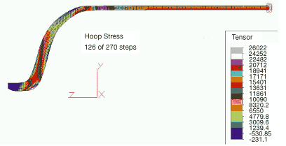
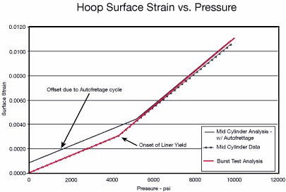
The next step is a nonlinear FEA of the layup. A simple linear analysis assumes that the material properties are constant at all load levels, and that the stress at any load level is independent of the load history. Linear analysis can be performed in a single step. "When the cylinder is first pressurized," says Olson, "the liner takes most of the load. Eventually the liner material yields, becoming plastic, and then the composite takes almost all of the load." The nonlinear analysis is performed in a number of steps to accurately capture the behavior as the aluminum yields. Olson uses ALGOR (ALGOR, Inc., Pittsburgh, Pa., U.S.A.) to create an axisymmetric solid model, with one group of elements for each wind angle.
The total thickness depends on a number of factors, including the liner geometry, minimum required burst pressure, cycle requirements, robustness requirements, and other parameters. A DOT-CFFC SCBA cylinder with a volume of 6.8L/415 in3 and a service pressure of 31 MPa/4,500 psi might typically have four helical plies, with wind angles between 10° and 20°, and 12 hoop wrap plies, for a total composite sidewall thickness of about 5.1 mm/0.2 inch. The typical liner thickness in the sidewall is 1.5 mm to 2.5 mm/0.06 inch to 0.10 inch.
Prototype manufacturing and testing
Once the initial design is completed, HEI fabricates prototypes for testing. HEI uses water-dispersed towpregs from Newport and TCR towpregs from ATK; fibers come from many suppliers, including Grafil Inc. (Sacramento, Calif., U.S.A.), Hexcel (Dublin, Calif., U.S.A.), Toyobo Co. Ltd. (Osaka, Japan), Toray Composite Materials America Inc. (Trophy Club, Texas, U.S.A.), Zoltek Corporation (St. Louis, Mo., U.S.A.), and others. HEI mainly uses aerospace-grade tows for their higher properties and lower variation, which translates into a lower weight cylinder. HEI also has evaluated heavier tow materials. Although cost is lower, both because the fibers themselves are less expensive and fewer tensioners are required on the winder, weight does increase.
The liner is procured from the same source the customer uses, most often a commercial manufacturer such as Hydrospin (Huntington Beach, Calif., U.S.A.) or Samtech International (Carson, Calif., U.S.A.). Occasionally the customer manufactures its own liners and will then supply them to HEI. The liner is cleaned, and a thin layer of epoxy or polyurethane paint is used to provide a dielectric barrier to prevent galvanic corrosion.
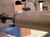
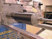
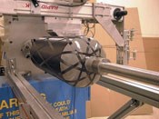
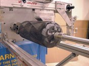
The painted liner is loaded into one of HEI's two filament winders, both of which are four axis units from Entec Composite Machines Inc. (Salt Lake City, Utah, U.S.A.). Development of the winding patterns takes about half a day. Winding with towpreg speeds up the process, because the tows stick to the mandrel without slipping or spreading. When the cylinder goes into production, the customer will spend more time tweaking and perfecting the winding patterns.
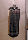
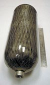
The liner is stiff enough so that it doesn't need to be pressurized for winding. In most designs, a hoop layer goes down first. One or two wraps are placed manually. Winding over those wraps locks the fiber in place. Most of the manual wrap is then cut off — if fiber builds up in this location, it creates a stress concentration, which could cause premature failure. Subsequent hoop and helical layers go down next. The initial hoop layers provide a good surface for the helicals (starting with helicals is possible, but it is more difficult to avoid wrinkles). Finally, a last glass layer is wound for damage resistance. The cylinder is then removed from the winder and hung in an oven for a vertical, no-rotation cure.
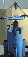
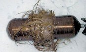
After cure, HEI subjects the cylinder to Level 1 testing, which includes the burst and cycle tests. The burst test is run first, and then the design might be tweaked depending on the results. Usually two or three iterations are required before HEI is satisfied with the design. When the design is complete, HEI assists the customer in building the first few cylinders and testing them for Level 2 qualification. Additional Level 2 tests include three drop tests, environmental cycling, thermal cycling, a gunfire test, and a bonfire test. In the gunfire test, the pressurized cylinder is shot with a 0.30 caliber armor- piercing projectile, and it must not fail by fragmentation. In the bonfire test, the pressurized cylinder is placed over an open fire and the gas must vent mainly through the installed pressure relief devices. In very rare cases, a cylinder will fail a Level 2 test. When that happens, the solution is almost always a minor design change, so it is not necessary to go back to Level 1 testing.
HEI's successes in the development of both wet- and towpreg-wound composite pressure vessels have made it a recognized leader in the field. In April 2003, NASA selected HEI to develop a new generation of tougher and safer composite pressure vessels under a Phase II Small Business Innovation Research (SBIR) contract. The first applications of the technology will be toward increased safety and oxygen storage capacity of SCBA tanks, lighter and safer storage systems for alternative fuel vehicles, and lower operating costs for all users of high-pressure cylinders.
Related Content
Nine factors to consider when designing composites cure tooling
Gary Bond discusses the common pitfalls and compromises when designing good cure tooling and their holistic significance for a robust composite production process.
Read MoreThe potential for thermoplastic composite nacelles
Collins Aerospace draws on global team, decades of experience to demonstrate large, curved AFP and welded structures for the next generation of aircraft.
Read MoreAirbus video highlights RACER compound helicopter first flight
Launched as part of a Clean Sky 2 program, a compound design — rotor, split fixed-wing, propulsive propellers — uses composites to cut fuel consumption and emissions by 20%.
Read MoreRocket Lab begins installation of large AFP machine for rocket production
The 99-ton AFP machine, custom-designed and built by Electroimpact, is claimed to be the largest of its kind, expecting to save around 150,000 manufacturing hours in the Neutron rocket’s production process.
Read MoreRead Next
“Structured air” TPS safeguards composite structures
Powered by an 85% air/15% pure polyimide aerogel, Blueshift’s novel material system protects structures during transient thermal events from -200°C to beyond 2400°C for rockets, battery boxes and more.
Read MoreDeveloping bonded composite repair for ships, offshore units
Bureau Veritas and industry partners issue guidelines and pave the way for certification via StrengthBond Offshore project.
Read MoreAll-recycled, needle-punched nonwoven CFRP slashes carbon footprint of Formula 2 seat
Dallara and Tenowo collaborate to produce a race-ready Formula 2 seat using recycled carbon fiber, reducing CO2 emissions by 97.5% compared to virgin materials.
Read More


