Tubular composite core stiffens launch vehicle structure
ChamberCore, an alternative to traditional sandwich laminates, also improves vibro-acoustic damping.
Share
The payload fairing on a launch vehicle protects the payload during ascent, maintaining it in a controlled environment. Although a simple monocoque laminate could otherwise provide sufficient environmental protection, the fairing is located at the front of the vehicle, so the construction must have a high stiffness to react the aerodynamic loads and prevent excessive vehicle bending. As a result, most modern payload fairings are constructed of a composite sandwich laminate, usually carbon/epoxy facesheets over a honeycomb or foam core. Conventional sandwich constructions provide acceptable stiffness but offer insufficient protection from acoustic vibration during take-off. "At launch, acoustic waves reflect from the ground and excite the vehicle, which, in turn, excites the payload," explains Joe Padavano, president of aerospace engineering firm Delta Velocity Corp. (Purcellville, Va., U.S.A.). The potential for damage to satellites and sensitive instru-mentation is high. According to the U.S. Air Force Research Laboratory (AFRL), researchers estimate that vibro-acoustic stress may account for nearly half of all payload failures that occur within the first 24 hours after launch. Reducing such stresses, therefore, could go a long way toward improving payload reliability and reducing launch risks. Furthermore, a payload fairing that better damped stresses would enable payload engineers to create lighter satellite structures, leaving more weight for sensors, propulsion units and other non-structural elements.
In pursuit of that goal, AFRL launched a small sounding rocket on Aug. 20, 2003 from Wallops Island Flight Facility, off the coast of Virginia, U.S.A. The Vibro-Acoustic Launch Protection Experiment (VALPE-2), as it was called, carried a number of new vibration isolation and acoustic mitigation technologies. Active system experiments designed by CSA Engineering (Mountain View, Calif., U.S.A.) and The Boeing Co. (Chicago, Ill., U.S.A.) monitored vibro-acoustic loads during launch and drove actuators to partially cancel out harmful loads. The VALPE-2 payload fairing, designed and built by Delta Velocity, was itself part of the experiment, designed to demonstrate a lightweight composite fairing based on ChamberCore, a unique manufacturing process that promises to significantly reduce vibro-acoustic stresses.
Updating an old idea
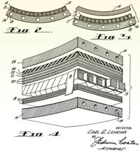
A ChamberCore laminate is basically formed by placing a number of square (or nearly square) composite tubes in parallel and bonding them together with composite facesheets. This construction achieves the stiffness of a sandwich laminate but also possesses unique geometric features that can be used to further reduce acoustic transmission.
The concept was originally developed by Douglas Aircraft Co. and patented in 1956. These "multi-ducted shells," as Douglas called them, were used for aircraft radomes. In the late 1990s, AFRL and Dr. Stephen Tsai (Stanford University, Stanford, Calif., U.S.A.) began developing a simplified ChamberCore manufacturing process. Later, AFRL determined that, by drilling holes through the inner skin into the hollow cores, a ChamberCore laminate could act as an acoustic damper (based on the same principles as a Helmoltz resonator).
In 2001, AFRL awarded a Small Business Innovation Research (SBIR) contract to Delta Velocity. Phase I required Delta Velocity to further streamline the design and manufacturing processes; Phase II would provide initial flight demonstrations of ChamberCore, first in the VALPE-2 fairing, and later in the larger Scorpius (Microcosm, El Segundo, Calif., U.S.A.) fairing.
Delta Velocity engineers came up with an alternative to drilling holes: by filling the cores with water, they realized they could reduce the acoustic loads even further. "Most payload fairings add mass, in the form of heavy acoustic blankets, to attenuate these loads," says Padavano. "The extra mass must be carried until fairing jettison -- about two to five minutes into flight -- but it is really only needed for the first 8 to 20 seconds." The Delta Velocity design would drain the ChamberCores after those first few seconds, reducing the effective flight mass and allowing for heavier payloads. The water-filled and Helmholtz modifications will be tested in the future. For now, the VALPE-2 and Scorpius fairings use standard ChamberCore.
Adapted software optimizes design
In Phase I of the SBIR contract, Delta began by sizing the ChamberCore tubes and facesheets for expected flight loads. Analysis methods are well defined for standard sandwich structures, but the unique ChamberCore geometry required new analytical techniques. The tube geometry introduces new failure modes, such as buckling of the walls between the tubes. The tubes and facesheets each can be made of a different layup, and possibly even different materials. Finally, the size of the tubes is also important -- if they are made too large or too small, the structure weighs more than is necessary.
Delta analysts used HyperSizer software from Collier Research Corp. (Hampton, Va., U.S.A.) to size the cores. HyperSizer is able to analyze the individual components of a stiffened panel, sizing each component to minimize weight while maintaining positive margins against dozens of failure modes. Although HyperSizer models six different panel families (honeycomb, corrugated, etc.), with a number of subtypes within each family, it does not include a ChamberCore panel. Instead, the ChamberCore panels were treated as I-beams (a supported model type) sandwiched between two facesheets. By making the gaps between the I-beam flanges very small, the resulting panel was a good approximation of the ChamberCore geometry. HyperSizer was able to analyze literally thousands of combinations of core height and width, core layups, and facesheet layups in a matter of minutes.
A T700/E-765 prepreg from FiberCote Industries Inc. (Waterbury, Conn., U.S.A.) was chosen for the tubes and facesheets because it had been qualified under the AGATE program and material property data was readily available (see "AGATE Methodology Proves its Worth," HPC May 2003, p. 38). Combinations of unidirectional and fabric plies were examined, but the HyperSizer analysis ultimately settled on an unusual +45°/-45° (antisymmetric) layup of unidirectional tape (0.127 mm / 0.005 inch ply thickness) for the cores and a three-ply, 0°/90°/0° tape layup for the facesheets. The core cross-section was square, with 23 mm (0.9 inch) sides.
Maximizing mandrel performance
AFRL fabricated the tubes for early ChamberCore tests by overwrapping a solid rubber mandrel with prepreg. The mandrel was made from Aircast 3700 (Airtech International, Huntington Beach, Calif., U.S.A.). This material is easy to cast into any shape, and its high thermal expansion coefficient provides good compaction pressure during cure. The wrapped cores were laid up between the facesheets and the entire structure was cocured under autoclave pressure. AFRL also tried curing the cores first, then placing them between uncured facesheets and curing the resulting structure. The latter method had the potential to reduce the number of mandrels needed -- the cores could be made in bulk, then placed between the facesheets without mandrels -- but the cores tended to deform under cure pressure without the internal mandrel support.
The rubber mandrels worked well for straight cores with small aspect ratios (relatively fat cross-sections). For typical aerospace structures, however, the cores would be smaller in cross-section and might bend or curve, as well. Preliminary tests indicated that pulling rubber mandrels out of such cores would be difficult, if not impossible. As an alternative, Delta decided to use water-soluble mandrels that could be washed out after cure. These mandrels would not expand like the rubber mandrels, but the autoclave pressure would provide sufficient compaction.
A flat test panel was made using core mandrels cast from Aquacore (Advanced Ceramics Research, Tucson, Ariz., U.S.A.), a water-soluble ceramic material that is environmentally friendly and requires no special disposal procedures. ACR built the mandrels for Delta Velocity by packing the material into a metal tool and then drying it in an oven. When the Aquacore material proved to be very brittle, the mandrels were reinforced with a thin metal rod through the center and overwrapped with a release tape to prevent flaking.
For the VALPE-2 fairing, ACR used a newer Aquacore formulation that was tougher and did not require an internal reinforcement. The bare cores were shipped to Composite Tooling Corp. (Albuquerque, N.M., U.S.A.), where Delta Velocity sprayed them with Aquaseal. This gave a smooth, less porous surface, eliminating the need for a release tape overwrap. The mandrels, however, absorbed moisture from the sealer, causing them to become flexible and warp. "We ended up spraying one surface at a time," explains Delta integration and test engineer Warren McCrary. "After that surface dried, we rotated the cores and sprayed the next surface, until all four sides were covered twice."
Fairing layup
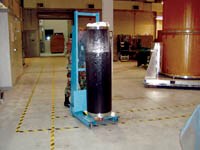
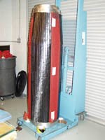
The VALPE-2 fairing is 1,524 mm/60 inches tall, with a 438-mm/17.25-inch outside diameter at the base. Roughly the lower two-thirds is a straight cylinder; the upper section is a truncated cone. A total of 60 core tubes, running vertically from the base of the cylinder to the top of the cone, are needed to span the circumference. The prepreg layers for the cylindrical and conical portions of each tube were laid up separately, with a splice at the cylindrical/conical transition. Each layer in the cylindrical portion is made with two pieces of prepreg to make up the required length, and each layer in the conical section is made with only one piece; the splices were two layers each at +45°/-45°, but were laid up as four individual pieces on each side of the core.
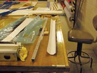
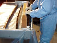
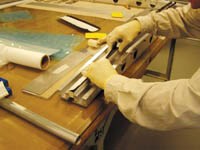
Achieving proper alignment of all the layers was difficult. First, the splice pieces were laid up onto the core mandrel. Next, the +45°/-45° layers were laid up flat so they could be applied in a single operation. The plies were then placed on a table against a straight edge, the core mandrel aligned over the plies using reference marks, and the mandrel pressed onto the plies for temporary adhesion. This entire assembly was next carried to a wrapping tool -- actually the same tool that had been used to cast the core mandrels. The layup assembly was pressed into the tool, which forced the prepreg tight against the mandrel and formed sharp corners. The remaining prepreg was pressed by hand against the top of the mandrel, with the overlap seam holding the prepreg in place. Many of the core mandrels cracked before or during the layup process, but the prepreg held everything together. The outer release paper was left on to prevent adhesion during storage.
After all of the cores had been wrapped, layup of the fairing itself was fairly simple. The inner facesheet was laid up directly on the tool, which was placed vertically so the cores could stick to the inner facesheet without falling off. A ply of release film was placed over the facesheet temporarily, so the cores could be positioned before being stuck to the facesheet. Groups of six cores were pressed together on a table, then placed onto the fairing. After each group was positioned properly, the release film was pulled out from behind the cores. Finally, the outer facesheet was laid up over the cores. The entire assembly was covered with a silicone sheet to help smooth the outer surface, then vacuum bagged and autoclave-cured at 121°C (250°F) for two hours.
Flight assembly
After cure, the fairing was shipped back to Delta Velocity's Virginia facility for final processing. The entire fairing was placed horizontally in a water bath to soften the cores. As the Aquacore material softened, the fairing was rotated, and high pressure water was sprayed into the upper cores to remove the material. Softening went slowly because only the ends of the cores were exposed to the water. After most of the Aquacore was dissolved, some material was left on the composite. "We attached a wire shotgun-cleaning brush to a drill and ran it through the cores," said McCrary. "That got rid of most of the loose material." The resin did penetrate into the Aquacore and could only be removed by picking at it with a knife. Ballast was to be added to the fairing anyway, in order to meet flight requirements, so the remaining Aquacore was just left in place.
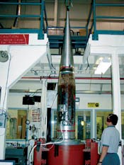
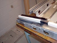
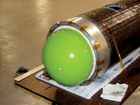
To attach the fairing to the vehicle and nosecone, complex machined, heavy aluminum rings had to be bonded onto both ends of the structure. "We were designing a composite structure to replace an existing metal structure," Padavano explains. "We had to match the existing interfaces, which were not optimal for a composite or sandwich structure." The fairing shell was placed on a rotary table (rotab) for the bonding operation. A "Christmas tree" jig located and aligned the metal rings on the shell. The Loctite (Henkel Loctite, Rocky Hill, Conn., U.S.A.) adhesive required a 0.15 mm to 0.30 mm (0.006 inch to 0.012 inch) bondline, but the fairing outside diameter was about 10 percent smaller than expected -- apparently the Aquacore material had shrunk during drying or compressed slightly during cure. To get back to the required bondline, a couple of layers of sacrificial fiberglass were laid up on either end of the fairing and then turned down on the rotab to the proper diameter.
Despite the use of the silicone rubber sheet during cure, the square cores resulted in a faceted surface, requiring some filling and sanding to smooth out rough spots. Furthermore, occasional divots in the Aquacore cores translated through to the surface and were filled in with a mixture of ground cork and epoxy. A perfectly smooth surface, however, was not required, because a 2.3 mm (0.09 inch) thick layer of cork was bonded and vacuum bagged onto the outer composite surface for thermal protection. Finally, the fairing was painted with a white conductive paint for static dissipation.
The successful launch of VALPE-2 proved the flight-worthiness of ChamberCore structures. "The goal was not so much to develop the structure," said Padavano. "Douglas Aircraft did that in the 1950s. Our main goal was to figure out a cost-effective method for building ChamberCore launch vehicle structures." The follow-up Scorpius launch will give Delta Velocity an opportunity to further refine the manufacturing method while also demonstrating ChamberCore on a larger structure.
Lessons learned
The core mandrels for the Scorpius fairing have already been cast, this time using a washaway salt-based material from
TI International Ltd. (North Chicago, Ill., U.S.A.). "The Aquacore material was not the optimum choice for our long, skinny mandrels. The TI International material has a better surface finish and is much denser, providing the strength necessary to withstand handling loads," explains Padavano.
"Moisture absorption is still an issue, though," McCrary notes. "If we leave the mandrels out in humid air, they warp and crack." Immediately after casting, therefore, the mandrels are sealed in a bag with desiccant. The salt material also dissolves faster if the water is heated to at least 57°C/135°F. Total washout time will probably remain the same, however, because the Scorpius cores are much longer than the VALPE-2 cores.
The most significant changes are being made in the layup process. For the VALPE-2 fairing, cutting the prepreg took three days and wrapping the cores took another three. The same steps for Scorpius would take more than twice the time: not only are the cores longer, but there also are twice as many. This time around, however, Mentis Sciences (Manchester, N.H., U.S.A.) will overbraid the cores with an ATK Composites (Clearfield, Utah, U.S.A.) TCR low-tack towpreg. Much simpler than hand cutting and wrapping, the braiding process also will eliminate the longitudinal seam on each core, resulting in greater tube integrity and strength. The facesheets will be laid up from a TCR high-tack prepreg fabric, further simplifying the layup process. Later fairings may have wound facesheets, resulting in even greater time savings.
These improvements in the manufacturing process are expected to reduce the cost of ChamberCore structures, making them more attractive as alternatives to traditional sandwich structures. Improvements in core uniformity and the overall layup will reduce structural weight and stiffness. These features make ChamberCore an attractive launch vehicle structure, even without the added acoustic benefits. Future experiments will further explore mass loading and Helmholtz resonators for acoustic attenuation.
Related Content
Plant tour: Joby Aviation, Marina, Calif., U.S.
As the advanced air mobility market begins to take shape, market leader Joby Aviation works to industrialize composites manufacturing for its first-generation, composites-intensive, all-electric air taxi.
Read MorePlant tour: Spirit AeroSystems, Belfast, Northern Ireland, U.K.
Purpose-built facility employs resin transfer infusion (RTI) and assembly technology to manufacture today’s composite A220 wings, and prepares for future new programs and production ramp-ups.
Read MoreWelding is not bonding
Discussion of the issues in our understanding of thermoplastic composite welded structures and certification of the latest materials and welding technologies for future airframes.
Read MoreComposites manufacturing for general aviation aircraft
General aviation, certified and experimental, has increasingly embraced composites over the decades, a path further driven by leveraged innovation in materials and processes and the evolving AAM market.
Read MoreRead Next
Plant tour: Daher Shap’in TechCenter and composites production plant, Saint-Aignan-de-Grandlieu, France
Co-located R&D and production advance OOA thermosets, thermoplastics, welding, recycling and digital technologies for faster processing and certification of lighter, more sustainable composites.
Read MoreDeveloping bonded composite repair for ships, offshore units
Bureau Veritas and industry partners issue guidelines and pave the way for certification via StrengthBond Offshore project.
Read MoreAll-recycled, needle-punched nonwoven CFRP slashes carbon footprint of Formula 2 seat
Dallara and Tenowo collaborate to produce a race-ready Formula 2 seat using recycled carbon fiber, reducing CO2 emissions by 97.5% compared to virgin materials.
Read More


