
Understanding the influence of fiber orientation on structural analysis of fiber-filled parts
The effect of fiber orientation on material properties is a key way the injection molding process impacts mechanical performance. Doug Kenik and Angie Schrader of the Design, Lifecycle & Simulation product group at Autodesk (Waltham, MA, US) illustrates two ways fiber orientation influences the structural behavior of fiber-filled parts and discuss the need for a bi-directional approach to design and analysis.

Doug Kenik works with the Design, Lifecycle and Simulation product group at Autodesk. Kenik is the product line manager for Autodesk’s composite simulation products and has been involved in both research and development of the technology within those products.

Angie Schrader works with the Design, Lifecycle and Simulation product group at Autodesk. Schrader works across simulation products on validation and special projects.
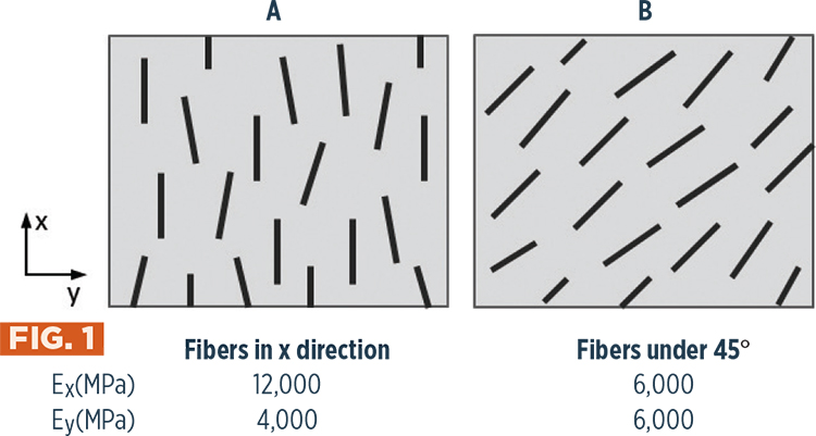
Fig, 1 - Fiber direction, Examples A and B
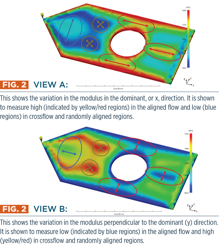
Fig. 2: Views A and B. View A shows the variation in the modulus in the dominant, or x, direction. It is shown to measure high (indicated by yellow/red regions) in the aligned flow and low (blue regions) in crossflow and randomly aligned regions. View B shows the variation in the modulus perpendicular to the dominant (y) direction. It is shown to measure low (indicated by blue regions) in the aligned flow and high (yellow/red) in crossflow and randomly aligned regions.
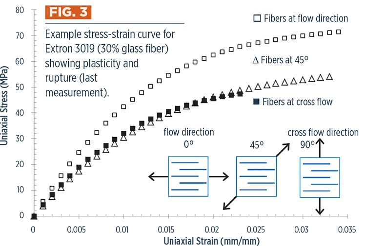
Fig. 3: Example stress-strain curve for Extron 3019 (30% glass fiber) showing plasticity and rupture (last measurement).
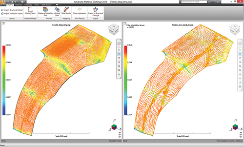
Fig. 4: A screen shot from Autodesk’s Advanced Material Exchange showing fiber orientation being mapped from manufacturing (right) to structural simulation (left).


Adding fiber reinforcement to plastic parts creates unique challenges for structural analysis. Variations in material properties and fiber orientations during injection molding processes can be significant but often are overlooked. The result is an over-simplification of the model that neglects key influences, such as weak areas due to weld lines, residual strains that cause warpage, and property variations due to fiber alignment. Therefore, parts are often overdesigned or must be optimized through trial and error. In a market where molders are looking to increase performance while reducing cost, those approaches are just not acceptable.
The effect of fiber orientation on material properties is a key way the injection molding process impacts mechanical performance. The following illustrates just two ways fiber orientation influences the structural behavior of fiber-filled parts and discusses the need for a bi-directional approach to design and analysis.


As the injected material flows through the mold, fiber alignment is affected by the direction of flow and the mold cavity geometry and can vary greatly throughout the part. The resulting fiber orientation has a direct correlation with mechanical properties. In Fig. 1, at left, Example A illustrates how areas with highly oriented fibers have a high modulus in the direction of orientation and a much lower one (one-third as high) in the cross-flow. In comparison, Example B illustrates that if fibers are largely 45° to the flow direction, the moduli are equal.
Fig. 2 shows how variation in fiber alignment results in significant variation in mechanical properties in even simple part geometry. With the gate location at the left point, the first area experiences expanding flow, and fiber orientation is largely perpendicular to the flow. This is followed by an area with more random alignment and, finally, areas where flow is predominantly in the flow direction. The result is a complex distribution of anisotropic mechanical properties, as shown in Views A and B.
Under mechanical loading, plastic parts typically exhibit a significant plasticity prior to rupture. When fibers are added, both plasticity and rupture loads are influenced by fiber orientation and loading direction. This is illustrated in the tensile test results shown in Fig. 3, where all three load directions show significant plastic response prior to rupture, but the stiffness and strength of the material show high dependence on the relative fiber direction. The plasticity of the specimen loaded in the fiber flow direction is clearly different than that of the fibers loaded at 45° or perpendicularly (90°). The strain-to-rupture loads are also different, with the specimen loaded in the cross-flow direction rupturing 33% sooner.
These examples demonstrate the need for structural simulation with insight into the after-molding or as-manufactured condition of the part and an ability to model the nonlinear material response. Simulation solutions are making great strides in providing these capabilities. For example, Autodesk Inc. (Waltham, MA, US) software can determine weld-line locations, fiber orientations from injection or compression molding and warpage due to cooling of a discontinuous-fiber-reinforced composite part. Siemens PLM Software Inc. (Plano, TX, US), Dassault Systèmes (Vélizy-Villacoublay, France), and ESI Group (Rungis, France) are able to inform users about ply orientations from a portion of the manufacturing process for continuous fiber-reinforced composites as well. There is work yet to be done on simulating the molding process in areas such as identifying a potential delamination from hand or tape layup and linking this information to curing to determine warpage and residual stresses.
The next critical step is transferring this as-manufactured information to the structural analysis. Many solutions for continuous-fiber composites only pass fiber orientation one way, from design to structural or to manufacturing simulations, but the as-manufactured information is not yet easily incorporated into the analysis. Solutions for discontinuous-fiber composites are further developed by the likes of e-Xstream engineering SA (Newport Beach, CA, US) and Autodesk, which offer software able to bring as-manufactured fiber orientations (Fig. 4), fiber volume fractions and warpage results from molding simulation to the structural simulation, providing more realistic results and valuable insight.


Related Content

Composite resins price change report
CW’s running summary of resin price change announcements from major material suppliers that serve the composites manufacturing industry.
Read More
VIDEO: One-Piece, OOA Infusion for Aerospace Composites
Tier-1 aerostructures manufacturer Spirit AeroSystems developed an out-of-autoclave (OOA), one-shot resin infusion process to reduce weight, labor and fasteners for a multi-spar aircraft torque box.
Read More
CompPair adds swift prepreg line to HealTech Standard product family
The HealTech Standard product family from CompPair has been expanded with the addition of CS02, a swift prepreg line.
Read More
PEEK vs. PEKK vs. PAEK and continuous compression molding
Suppliers of thermoplastics and carbon fiber chime in regarding PEEK vs. PEKK, and now PAEK, as well as in-situ consolidation — the supply chain for thermoplastic tape composites continues to evolve.
Read MoreRead Next

“Structured air” TPS safeguards composite structures
Powered by an 85% air/15% pure polyimide aerogel, Blueshift’s novel material system protects structures during transient thermal events from -200°C to beyond 2400°C for rockets, battery boxes and more.
Read More
All-recycled, needle-punched nonwoven CFRP slashes carbon footprint of Formula 2 seat
Dallara and Tenowo collaborate to produce a race-ready Formula 2 seat using recycled carbon fiber, reducing CO2 emissions by 97.5% compared to virgin materials.
Read More
VIDEO: High-volume processing for fiberglass components
Cannon Ergos, a company specializing in high-ton presses and equipment for composites fabrication and plastics processing, displayed automotive and industrial components at CAMX 2024.
Read More