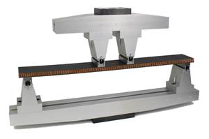
V-Notch Rail Shear test (ASTM D 7078-05)
Dr. Don Adams introduces HPC readers to the The V-Notched Rail shear test method, approved as ASTM Standard D 7078-05 by ASTM Committee D-30 in March of 2005.
The latest of the ASTM standards for determining the shear strength and shear stiffness of materials — composite materials in particular — has just been released. The V-Notched Rail shear test was approved as ASTM Standard D 7078-05 by ASTM Committee D-30 in March of this year1.
The reader’s first question has to be, Why do we need another shear test method for composite materials? There are already several dozen in existence, with at least a dozen of them in use today2, all intended to measure the same material property. In a future article, we will compare and contrast the more commonly used of these various shear test methods. At that time the question will be, Which is the ”best” of these many shear test methods? Presently, however, we will stick with the first question.
The new V-Notched Rail shear test method is essentially a combination of the best features of two of the more commonly used methods, viz., the Iosipescu Shear and the Two-Rail Shear test methods, eliminating, in the process, certain weaknesses of each.
The Iosipescu Shear test method was originally developed for isotropic materials by Nicholi Iosipescu3 in Rumania in the early 1960s, but remained relatively unknown. Years later, and after more than 10 years of extensive development for use with composite materials4,5, it became ASTM Standard D 5379 in 19936. In the now more than a dozen years since its standardization, the Iosipescu Shear test method’s versatility and accuracy have made it one of the preferred shear test methods for composite materials.
Another shear test method for orthotropic materials, the Two-Rail Shear test method7, has been an ASTM standard even longer than the Iosipescu Shear test method, having been introduced as ASTM D 4255 in 19838, also after a long period of development.9
A weakness of the Iosipescu Shear test method is that the specimen is loaded by concentrated forces on its edges. In some cases, this can lead to edge-crushing. To guard against edge crushing, the user may bond doublers (tabs) at each end of the specimen to increase the load-bearing area, but this is a time-consuming and costly procedure. These concentrated forces can also disturb the uniform stress state within the gage section. Another weakness is the relatively small gage section of the specimen.
The primary weaknesses of the Two-Rail Shear test method are that a uniform shear stress is not developed within the specimen and stress concentrations are induced in the regions where the rails are clamped onto the specimen. Secondarily, the method requires a relatively large specimen and the user must drill multiple holes in the specimen to permit bolting of the rails onto the specimen edges.
On the other hand, these two test methods also have their respective strengths. The Iosipescu Shear test specimen incorporates V-notches, which result in a relatively uniform shear stress state within the gage section between the notches. The Two-Rail Shear test specimen is loaded on its faces, eliminating the problem of edge crushing.
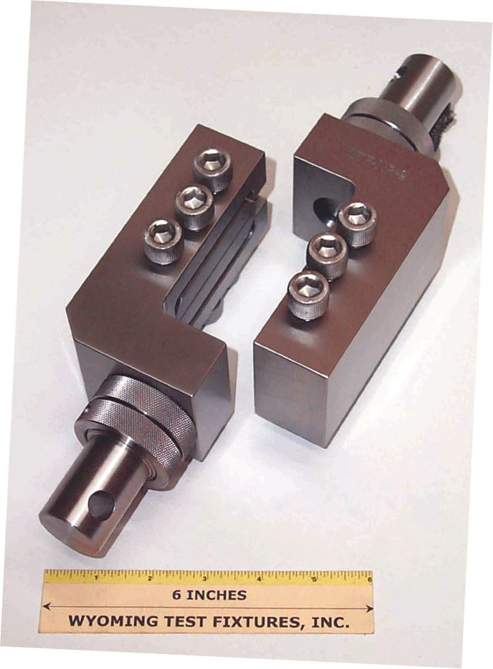
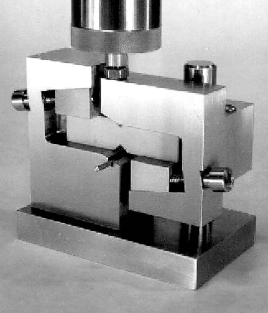
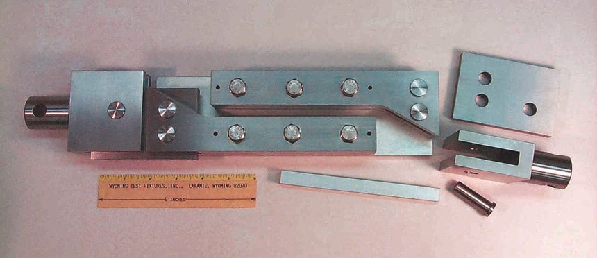
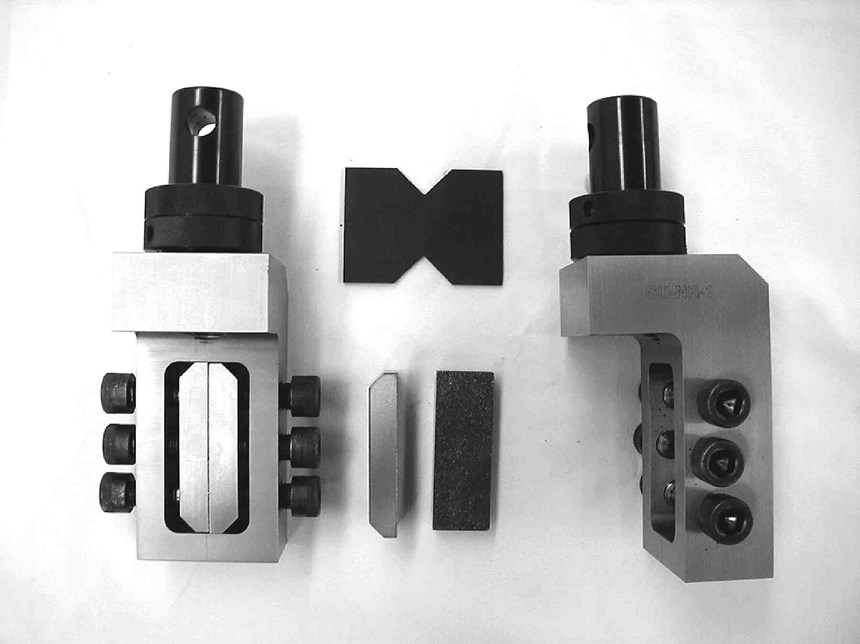
The new V-Notched Rail Shear test method simply combines these strengths. The resulting test fixture and specimen are shown in Fig. 1, with another view of the fixture in Fig. 2. For comparison, the Iosipescu Shear fixture, with a specimen installed, is shown in Fig. 3, and the Two-Rail Shear fixture, with a specimen partially installed, is shown in Fig. 4.
The similarity of the V-Notched Rail Shear specimen to the Iosipescu Shear specimen is obvious. Both specimens are 76 mm/3 inches long. Also, the ratio of notch depth to total specimen depth (0.225) is similar to that for the Iosipescu Shear specimen (0.200). However, the distance between the notch roots is significantly greater, 31 mm/1.22 inches vs. 11.4 mm/0.45 inches, resulting in a gage section that is 2.7 times greater, even though both specimens are the same length. This is possible because of the more efficient specimen gripping provided by the V-Notched Rail Shear fixture.
Likewise, the V-Notched Rail Shear fixture has similarities to the Two-Rail Shear fixture. Both grip two opposing edges of the specimen between pairs of rails. However, for the V-Notched Rail Shear fixture, no holes in the specimen are required. The fixture clamping screws push against gripper plates, rather than passing through the specimen. This simplifies specimen preparation and eliminates potential stress concentrations induced by holes in the specimen.
The standard Two-Rail Shear specimen is rectangular, 152 mm/6 inches long by 102 mm/4 inches wide. Thus it consumes 3.6 times more test specimen material than the V-Notched Rail Shear specimen. This may or may not be significant in a particular application. However, the fact that the specimen is a simple rectangle rather than one containing V-notches is significant. The shear stress at each free end of the rectangular specimen must be zero, since these are free surfaces. Thus, the shear stress cannot be uniform along the entire length of the specimen gage section.
On the V-Notched rail shear fixture, the gripping plate surfaces that contact the test specimen are coated with 60-grit tungsten carbide particles. Roughly comparable to 60-grit emery cloth, this coating will not significantly degrade the untabbed surfaces of the test specimen even when high clamping forces are used. And tungsten carbide, being a very hard material, offers extended life of the gripping plate surfaces before they need to be re-coated. Using the standard ASTM specimen size, these gripping surfaces have permitted the successful testing of composite materials such as ±45° laminates that have shear strengths in excess of 500 MPa/75 ksi10. No other shear test method can approach this capability.
This test method was developed as a joint effort between the University of Wyoming (Laramie, Wyo.) and the University of Utah (Salt Lake City, Utah), as referenced in ASTM D 7078.
References
1ASTM Standard D 7078-05, “Shear Properties of Composite Materials by the V-Notched Rail Shear Method,” American Society for Testing and Materials, W. Conshohocken, Pa., (first issued in 2005).
2Adams, D.F., and Lewis, E.Q., “Current Status of Composite Material Shear Test Methods,” SAMPE Journal, Vol. 31, No. 6, January/February 1994, pp. 32-41.
3Iosipescu, N. “New Accurate Procedure for Single Shear Testing of Metals,” Journal of Materials, Vol. 2, No. 3, September 1967, pp. 537-566.
4Adams, D.F., and Walrath, D.E., “Further Development of the Iosipescu Shear Test Method,” Experimental Mechanics, Vol. 27, No. 2, June 1985, pp. 113-119.
5Adams, D.F., and Walrath, D.E. “Current Status of the Iosipescu Shear Test Method,” Journal of Composite Materials, Vol. 21, June 1987, pp. 494-507.
6ASTM Standard D 5379, “Shear Properties of Composite Materials by the V-Notched Beam Method,” American Society for Testing and Materials, W. Conshohocken, Pa., (first issued in 1993).
7Hussain, A.K., and Adams, D.F., “An Analytical and Experimental Evaluation of the Two-Rail Shear Test for Composite Materials,” Report UW-CMRG-R-98-105, Composite Materials Research Group, University of Wyoming (Laramie, Wyo.), February 1998.
8ASTM Standard D 4255, “Inplane Shear Properties of Composites Laminates,” American Society for Testing and Materials, W. Conshohocken, Pa., (first issued in 1983).
9Adams, D.F., “Evolution of a Test Method – The ASTM D 4255 Two-Rail Shear Test,” American Society for Composites, 15th Annual Technical Conference (College Station, Texas), September 2000.
10Adams, D.O., Moriarty, J.M., Gallegos, A.M., and Adams, D.F., “Development and Evaluation of the V-Notched Rail Shear Test for Composite Laminates,” Final Report No. DOT/FAA/AR-03/63, Federal Aviation Administration, Atlantic City International Airport (Atlantic City, N.J.), September 2003.
Related Content
Notched testing of sandwich composites: The sandwich open-hole flexure test
A second new test method has been standardized by ASTM for determining notch sensitivity of sandwich composites.
Read MorePhotothermal tomography for locating, quantifying defects in composites
Years of infrared testing development result in thermography technology that is no longer just qualitative, but can define defect size and depth, making additional UT scans obsolete.
Read MoreTesting to support composite bolted joint analysis
An overview of ASTM Standard Guide D8509, and its coupon-level mechanical testing of design properties for analyzing composite bolted joints.
Read MoreCrashworthiness testing of composites: A building block approach, Part 2
Following the previously discussed coupon-level testing element, subcomponent and component testing are the next steps in designing crashworthy composite structures.
Read MoreRead Next
VIDEO: High-volume processing for fiberglass components
Cannon Ergos, a company specializing in high-ton presses and equipment for composites fabrication and plastics processing, displayed automotive and industrial components at CAMX 2024.
Read MoreAll-recycled, needle-punched nonwoven CFRP slashes carbon footprint of Formula 2 seat
Dallara and Tenowo collaborate to produce a race-ready Formula 2 seat using recycled carbon fiber, reducing CO2 emissions by 97.5% compared to virgin materials.
Read More“Structured air” TPS safeguards composite structures
Powered by an 85% air/15% pure polyimide aerogel, Blueshift’s novel material system protects structures during transient thermal events from -200°C to beyond 2400°C for rockets, battery boxes and more.
Read More
