Vacuum bagging: The basics
A primer on the reasons to use vacuum bagging in composite part manufacture, and the basics of how to do it
Editor’s note: This content was originally published on NetComposites.com. NetComposites was acquired by CompositesWorld’s parent company, Gardner Business Media, in February 2020.
There are three main purposes for vacuum bagging during composites manufacture:
- Application of compaction pressure to consolidate plies
- Extraction of moisture, solvents, and volatiles from curing composite
- Allow resin to flow and be absorbed without hydraulic lock.

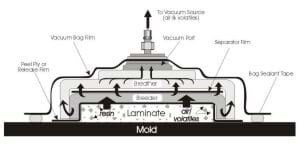
Figure 1.
The maximum compaction pressure available at sea level with a perfect vacuum bag is 14.7 psi (29.92 inches or 760 millimeters of mercury.) This maximum available pressure drops approximately 0.5 psi (1 inch or 25.4 millimeters of mercury) for each 1,000 foot gain in altitude. The routes for extraction of gases and resins is shown in Fig. 1.
The compaction pressure provided by a vacuum bag is crucial for good quality parts, when they are cured in a vacuum bag only. However, in an autoclave cure, much higher pressures are routinely available, up to several hundred psi for some types of solid laminates. However, the vacuum bag is still required in these circumstances, to extract the gases and reduce porosity.

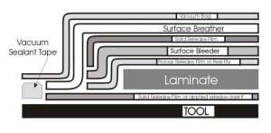
Figure 2.
How to sequence and use the variety of materials used in vacuum bagging can be one of the most confusing aspects in performing composite repair. The sequence of materials used is called the bagging schedule, as seen in Fig. 2.
Release film or peel ply
The first layer that goes against the uncured laminate is a release film or a peel ply that is used as a barrier between the laminate and the subsequent bleeder or breather layers. This layer can be non-porous or porous material depending on whether or not resin bleed is necessary. Often a perforated release film is used for a controlled resin bleed. The diameter and the spacing of the holes can vary depending on the amount of resin flow desired. A porous peel ply is used when you do not wish to restrict the resin bleed and/or a peel ply surface texture is required. A non-porous peel ply (commonly known as FEP, fluorinated ethylene propylene or Teflon) is used when no resin bleed is required, but evacuation of the volatiles and solvents is desired. This layer usually extends beyond the edge of the layup and can be sealed and/or secured with flashbreaker (FB) tape as required.
Bleeder layer
The bleeder layer is used to absorb resin from the laminate either through a porous peel ply or a perforated release film as described above. The bleeder layer is usually a non-woven synthetic fiber material that comes in a variety of different thicknesses and/or weights that range from between 2 oz./yd2 to 20 oz./yd2. Multiple layers can also be utilized for heavy resin bleed requirements. This layer usually extends beyond the edge of the layup and is secured in place with FB tape as required.
Separator film layer
The separator layer is used between the bleeder layer and the subsequent breather layer to restrict or prevent resin flow. This is usually a solid or perforated release film that extends to the edge of the layup, but stops slightly inside the edge of the bleeder layer, to allow as gas path to the vacuum ports. Non-porous FEP can also be used as a separator layer.
Breather layer
The breather layer is used to maintain a “breather” path throughout the bag to the vacuum source, so that air and volatile can escape, and so continuous pressure can be applied to the laminate. Typically synthetic fiber materials and/or heavy fiberglass fabric is used for this purpose. The breather layer usually extends past the edges of the layup so that the edge-band makes contact with the bleeder ply around the separator film. The vacuum ports are connected to the breather layer either directly or with strips that run up into the pleats of the bag. It is especially important that adequate breather material be used in the autoclave at pressure.
Bag film and sealant tape
The bag film is used as the vacuum membrane that is sealed at the edges to either the mold surface or to itself if an envelope bag is used. A rubberized sealant tape or putty is used to provide the seal at the periphery. The bag film layer is generally much larger than the area being bagged as extra material is required to form pleats at all of the inside corners and about the periphery of the bag as required to prevent bridging. Bag films are made of nylon, Kapton, or P.V.A. (polyvinyl alcohol) materials.
In addition to bagging schedules, there are other issues in vacuum bagging:
- Thermocouple quantity and placement
- Caul plates
- Heat blanket issues
- Heat sinks
- Extra adhesive layers
- Vacuum port quantity and placement
- Bagging “pleats”
- How much vacuum to draw
There are no quick and easy answers here. The bagging schedules used with wet layup repairs are affected by the ambient temperature as well as the pot life and amount of resin used. With prepreg repairs, the shelf life of the prepreg as well as its out-time “B-stage” affect the bagging schedule. Also, older but still certified prepreg may require a different schedule than fresh prepreg. The best practice is to test first whenever in doubt.
Related Content
PEEK vs. PEKK vs. PAEK and continuous compression molding
Suppliers of thermoplastics and carbon fiber chime in regarding PEEK vs. PEKK, and now PAEK, as well as in-situ consolidation — the supply chain for thermoplastic tape composites continues to evolve.
Read MorePultrusion: The basics
A primer describing what pultrusion is, its advantages and disadvantages, and typical applications.
Read MoreCelebrating 30 years of CompositesWorld, Part 1
CW explores key composite developments that have shaped how we see and think about the industry today.
Read MoreComposites end markets: Aerospace (2023)
With COVID in the past and passengers flying again, commercial aircraft production is ramping up. The aerocomposites supply chain is busy developing new M&P for an approaching next-generation aircraft program.
Read MoreRead Next
Developing bonded composite repair for ships, offshore units
Bureau Veritas and industry partners issue guidelines and pave the way for certification via StrengthBond Offshore project.
Read MoreAll-recycled, needle-punched nonwoven CFRP slashes carbon footprint of Formula 2 seat
Dallara and Tenowo collaborate to produce a race-ready Formula 2 seat using recycled carbon fiber, reducing CO2 emissions by 97.5% compared to virgin materials.
Read More“Structured air” TPS safeguards composite structures
Powered by an 85% air/15% pure polyimide aerogel, Blueshift’s novel material system protects structures during transient thermal events from -200°C to beyond 2400°C for rockets, battery boxes and more.
Read More


