Tooling is one of the most rapidly evolving segments of composites manufacturing across industries, as materials suppliers, service providers, toolbuilders and manufacturers develop, adopt and adapt to new technologies and processes to cut costs and speed deliveries. A few of the new technologies reshaping composites tooling design are 3D printing, out-of-autoclave infusion and the rise of thermoplastic composites for automotive and aerospace applications.
3D printing composite tooling
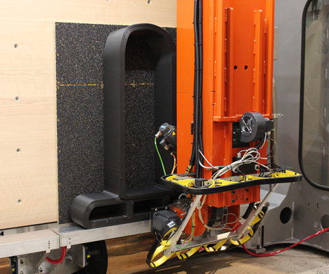
Thermwood Corp. (Dale, Ind., U.S.), a manufacturer of CNC machinery and large-scale additive manufacturing (LSAM) technology, recently introduced a higher-capacity LSAM print head with an output of up to 570 lb./hr. of composite material. The principle component of the higher capacity unit is a 60-millimeter melt core, which is interchangeable with the standard 40-millimeter print head melt core with a maximum output of 210 lb./hr. The higher capacity print head can print up to 100 feet of bead per minute, compared to about 50 ft./min. with the standard head.
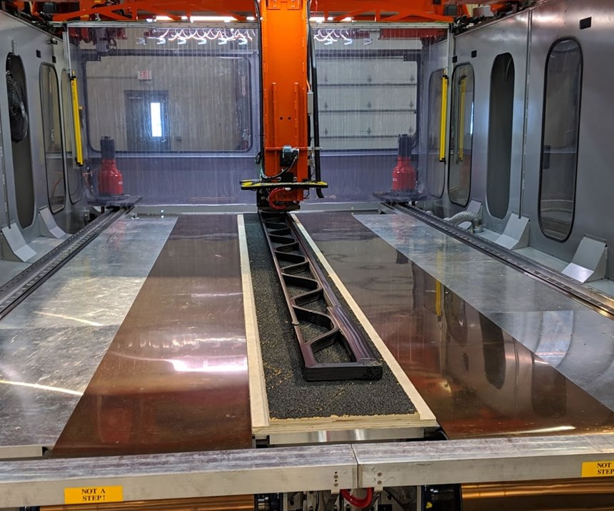
Thermwood employed the larger melt core to print half of a test tool for a Bell Helicopter Textron (Fort Worth, Texas, U.S.) helicopter blade. For this application, the high print rate facilitates orienting the print bead along the length of the tool, a crucial processing parameter for a large carbon fiber-reinforced part as thermal expansion is significantly lower in this direction. The tool, measuring 20 feet long by 14 inches wide by 17 inches high, was built from Techmer PM’s (Clinton, Tenn., U.S.) 25% carbon fiber-reinforced polyethersulfone (PESU) in a single continuous run requiring a total print time of only 3 hours, 9 minutes, with a final “as printed” weight of 542 pounds.
The carbon fiber-filled PESU material, a new product offering from Techmer PM, has a glass transition temperature (Tg) of 205°C and was specified to meet Bell’s autoclave requirements for curing the part at 182°C and 90 psi. Thermwood’s LSAM machine is equipped with a CNC router, which provided a seamless transition to machining and trimming the printed tool, an operation that required an additional 40 hours of machine time. The surface finish requirement for the tool was 32 RMS or better. Bell required tight tolerances to ensure the vacuum integrity required for autoclave cure.
Jason Susnjara, vice president of marketing at Thermwood, says after machining the tool, the vacuum integrity of the tool was physically checked and confirmed by bagging the tool and applying a vacuum. The tool was displayed at the Composites In Action — 3D Printing Area at JEC World 2019 (see CW’s video coverage of this from the show). “We will be printing the second half of the tool shortly,” Susnjara says, reporting that Bell will use the complete tool to manufacture a test part in an autoclave, then debrief Thermwood on the results and discuss the next steps in applying the technology. “This is a game changer,” says James Cordell, manager of manufacturing engineering at Bell. “Being able to print, machine and utilize tools in weeks in lieu of months will revolutionize the look at tooling going forward.”
Thermwood also recently announced full commercialization of a new feature of its LSAM technology, called vertical layer printing (VLP), in which beads of resin are laid vertically, side by side, rather than horizontally. VLP, which is restricted to the print head paired with a 40-millimeter melt core, is accomplished through the addition of a second moving table, mounted perpendicular to the main, fixed horizontal table. While the layers are being printed, the vertical table indexes, moving after each vertical layer of the part is completed, growing the part along the length of the machine.
The main benefit provided by VLP is the printing of certain types of long parts — for example, a tool for a boat hull can be printed in a single piece. By contrast, with horizontal layer printing, a boat hull is printed “upwards,” meaning standing on its transom. As the print envelope in this direction is only about 5 feet, the hull tool must be printed in sections that are then bonded together. This method not only adds considerable production time and cost, but can be problematic for higher-temperature materials, which are generally too resistant to chemicals and solvents to bond with enough integrity for use in an autoclave.
Out-of-autoclave molding
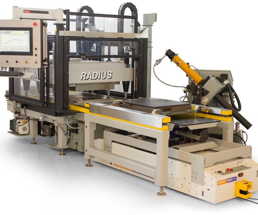
Now on the market for about 10 years, Same Qualified Resin Transfer Molding (SQRTM), a process developed and patented by Radius Engineering Inc. (Salt Lake City, Utah, U.S.), is a closed mold, out-of-autoclave (OOA) manufacturing method that provides an alternative to resin transfer molding (RTM) in an autoclave for production of high-tolerance aerospace parts. With SQRTM, the same resin used to prepreg the fiber is injected into the mold and provides the hydrostatic pressure required to consolidate the laminate. “Same Qualified” refers to SQRTM’s use of prepreg, which can be same qualified for program-specific parts and applications, versus RTM’s use of a dry preform requiring resin infusion.
Sonaca Engineering (Gosselies, Belgium) recently applied the SQRTM process in the manufacture of a demonstration wing slat integrated with electrical deicing. The net-shaped part features a titanium skin that is integrated directly into the mold and cure cycle. It is designed to reduce parasitic wing drag and cost via parts consolidation. Chad Frazier, product manager of composite tooling and development, says the project highlights the capabilities of SQRTM by producing a part that would be difficult and costly to make in an autoclave. “It’s a fairly complicated structure with stringent tolerances which benefits from our closed, matched tooling, process control and ability to integrate many features in a multi-tiered structure,” he says.
SQRTM tools are made from steel or aluminum and usually incorporated into a turnkey work cell. Radius is currently working on incorporating more sophisticated automation into the work cells, specifically in the areas of tool handling and setup. Jeff Perkins, workcell product manager, says new tool designs feature fully automated removal of the tool half and coupling of integral fluid packages. “We are working with suppliers and taking some of the lessons learned from the injection molding industry and applying them to closed mold tooling,” he says.
Airtech (Huntington Beach, Calif., U.S.) is a composite molding materials supplier offering customers a full line of materials and accessories for tooling used for autoclave molding at temperatures in the range of 400 to 425°C, primarily for its core aerospace market. Technical service manager Jerry Jackson says the success of the Airbus A220 aircraft, which features wings manufactured by Bombardier using dry fiber composites and a patented resin infusion process, is driving interest in transferring use of infusion to other high-volume commercial aircraft platforms. “There is still doubt if it will be adapted at that level, but the technology is growing and will be disseminated,” Jackson says. A switch to OOA resin infusion, at least for aerospace parts, should not change much in the way of current tooling requirements, he says. “The infusion and cure of the parts is taking place at elevated temperatures, so the same materials are relevant,” noting the design of this tooling is driven by CTE and the glass transition temperature of the tooling materials.
Tooling technology for thermoplastics
As the automotive and aerospace industries use thermoplastic composites for more and larger applications, tooling design and control technologies are being adapted to meet the needs of these materials.
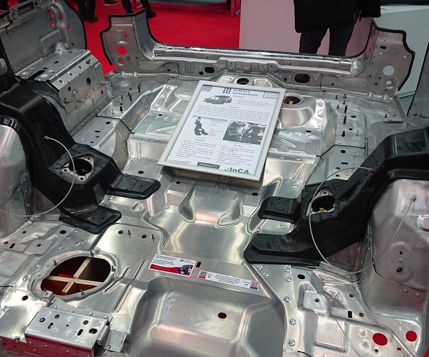
One of the holy grails of composites manufacturing is to supply structural parts for high-volume commercial automobiles to replace materials such as steel and aluminum. Surface Generation (Rutland, U.K.) is using its Production to Functional Specification (PtFS) thermal control processing technology in a demonstration/assessment project with Jaguar Land Rover Ltd. as part of an Innovate UK-funded research program — formally called the Thermoplastic Overmolding for Structural Automotive Applications (TOSCAA) — to manufacture a large thermoplastic composite reinforcing panel by overmolding discontinuous carbon fiber/PA6 onto unidirectional(UD) carbon fiber/PA6 prepreg inserts.
Surface Generation’s PtFS technology is aimed at addressing a fundamental problem to all composites molding, and perhaps plastics processing in general: Differential heating and cooling of the part during melt and consolidation. This inherent thermodynamic instability of composites molding processing not only can create deformations in part dimensions and properties, but can also wreak havoc on production costs, as one of the workarounds is to over-engineer the part by adding extra material. The problem is especially acute, says Surface Generation CEO Ben Halford, for parts designed with various thicknesses, multiple materials or with complex geometry. That said, Halford notes, even a component as simple as a flat, two-dimensional part, such as a laptop cover, has corners, a middle and edges that heat and cool at different rates.
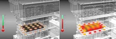
PtFS, which Halford describes as “rapid heat/cool with highly localized thermal control,” uses what he calls “pixels” of energy formed by jets of heated or cooled air arranged behind the mold surface. This pixelated architecture is then manipulated by software that incorporates Boolean logic to give precise heating and cooling rates — for example, a command might be: “To eliminate residual stress, I need all the part’s various areas and thicknesses (“zones”) to be within X degrees Fahrenheit for Y seconds, then I will compress the part and eject.” Ideally, the technology is integrated during the tool build, but it can also be retrofitted on existing hardware to improve quality. “Once this pixelated architecture is in place, you can drop your project-specific mold face forms on it for either single-sided vacuum processes or match-tooling compression molding,” says Halford. While acknowledging that competing suppliers also offer thermal mold control processing, Halford claims PtFS is distinguished by the scale of “tens to hundreds of thermally-controlled zones versus the control of two or three.” (See “Pixelated temperature control” for more on the PtFS process.)
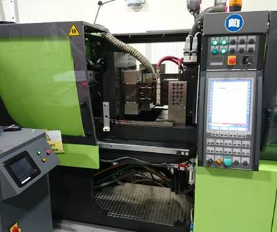
For the TOSCAA structural reinforcing panel project, Surface Generation partnered with a consortium of suppliers. (See “Overmolding for automotive” for more on this project and consortium). The existing part being assessed for replacement is a 3-millimeter thick, rear C-pillar structural reinforcement panel, approximately 1 meter long and between 0.5 and 0.25 meter in width, weighing 1.081 kilograms, formed from aluminum alloy sheet. The replacement composite part, technically a demonstrator article (DA), comprises four, 4.5-millimeter-thick reinforcing inserts made from Sigrafil C T50 prepreg tape in a PA6 matrix, supplied by SGL Group (Wiesbaden, Germany), overmolded with short (0.3 millimeter), carbon fiber-filled PA6. The thickness of the part varies from 2 millimeters in the unreinforced sections to 6 millimeters. The part was molded on an Engel Duo 1,700-ton injection molding machine at the National Composites Centre (NCC; Bristol, U.K.). Unlike many metal-to-composite demonstration projects, the principal objective was not weight reduction — the final carbon fiber-reinforced part weight approximately the same as the aluminum part. Instead, the project objective was to prove improved structural performance. Weight may be reduced at a later stage with higher-performing materials.
A 192-channel (96-zone) thermal-control PtFS system was integrated into the steel overmolding tool used to make the parts. Each of the carbon fiber inserts was designed with a “scarf” joint around the periphery to enhance bonding between it and the filled PA6 overmolding matrix. Halford says the zonal temperature control facilitated by PtFS was exploited to ensure optimum bond strength between continuous fiber reinforcement and the overmolding material. The thermal control system also keeps the average tool temperature higher during injection, permitting a reduction of clamping force and injection pressures required to fill the mold. Halford estimates that less than a quarter of the total clamping force of 1,700 tons was needed to mold the parts for the TOSCAA project. Halford says an economic analysis performed concurrently with the project validates the commercial viability of PtFS-enhanced overmolding used here. If, as anticipated, the ongoing assessment is successful, he says the supply chain comprising the project is positioned to ramp up and address any remaining barriers to full commercialization, with potential volumes as large as 10,000 to 100,000 parts per year.
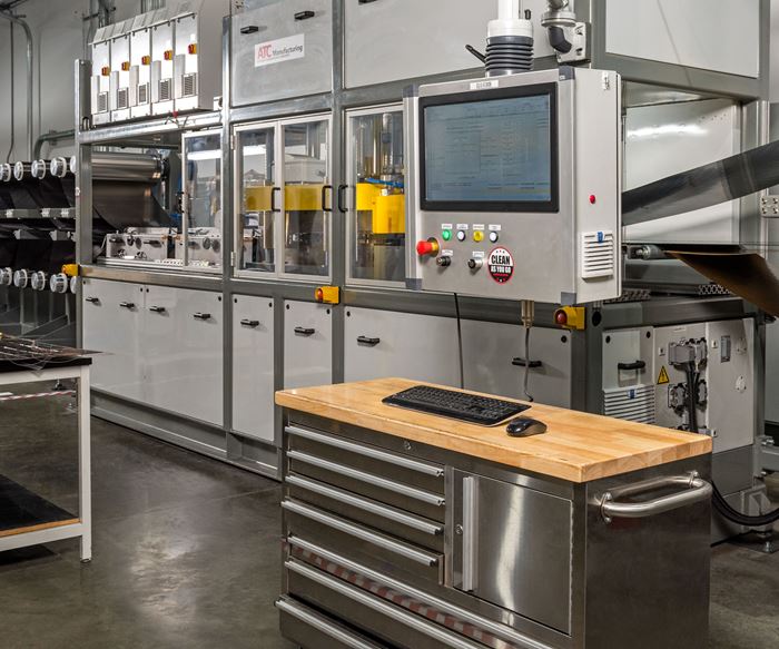
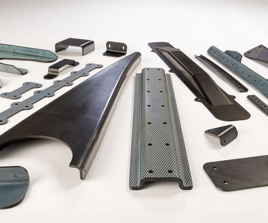
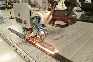
In the aerospace industry, ATC Manufacturing (Post Falls, Idaho, U.S.) makes a variety of thermoplastic composite parts for the aerospace industry using its in-house continuous compression molding (CCM) process. ATC’s inventory of parts includes various types of clips and brackets for hydraulic and electrical lines, to larger structural ribs and C-channel parts, some as long as 25 feet, used for joining even larger structural components such as wing skins. The primary factor driving the adoption of thermoplastic composites, says David Leach, ATC director of business development, is cost reduction, primarily on the labor side. “If you can get the materials into a laminate or sheet then you can form it into parts very quickly,” he says. This is compared to thermoset composites processing, which normally involves time-consuming layup, bagging and autoclave cycles.
The parts, which comprise both secondary and primary structures, are formed from laminates made from UD carbon fiber prepreg tape, as well as glass and carbon fabrics impregnated with polymers such as PEI and PPS (secondary) and PEEK and PEKK (primary). ATC buys the UD prepreg tapes and fabric laminates from several suppliers, such as Solvay (Alpharetta, Ga., U.S.), Toray Advanced Composites (Tokyo, Japan) and Teijin (Tokyo). Because of the resins’ high melting temperatures, the forming takes place at temperatures well above those used for thermosets, at 370°C and higher, which requires the use of steel or aluminum tooling. Typically, the laminate is heated above its melt temperature, quickly transferred to a rapid-closing press and kept at a constant temperature in the range of 205 to 260°C, which forms and cools the part at the same time. While the part is still hot, it is stable enough to remove from the tool and enable molding of the next part. Time is also saved by avoiding cycling the tool temperature and having to wait for the tool to recover to its processing temperature.
ATC designs the tooling but outsources tool fabrication. One of the trickier elements in building tooling for high-temperature TPC molding is compensating for the different rates of thermal expansion, in both the tooling and the composite materials.
“You have such a large difference from the temperature of the laminate blank to the tool temperature to the part service temperature that you have to put in a lot of thermal compensation design into the tooling components in order to allow for the contraction of the material,” Leach reports. Some thermoplastic materials can have up to three coefficients of thermal expansion (CTEs) — one at crystallization, another above the polymer glass transition temperature, and one more as the material cools to room temperature. The ability to accurately model and predict the shrinkage properties of the materials became even more critical as the company began making structural parts with more stringent tolerances. Leach says there was much trial and error required to develop proprietary thermal modeling software the company now uses to account for all thermally induced dimensional changes and achieve the required angular and dimensional tolerances. “We can typically achieve ±1 degree angular and 0.010 inch surface tolerance requirements,” Leach says.
It is clear that suppliers of tooling materials, tooling equipment and the tools themselves are under increasing pressure to help speed composites throughput, reduce costs and tighten dimensional control. This pressure will only increase as OOA and thermoplastic technologies continue to evolve. Suppliers, it appears, are poised to answer the call.
Related Content
Automated robotic NDT enhances capabilities for composites
Kineco Kaman Composites India uses a bespoke Fill Accubot ultrasonic testing system to boost inspection efficiency and productivity.
Read MoreActive core molding: A new way to make composite parts
Koridion expandable material is combined with induction-heated molds to make high-quality, complex-shaped parts in minutes with 40% less material and 90% less energy, unlocking new possibilities in design and production.
Read MoreATLAM combines composite tape laying, large-scale thermoplastic 3D printing in one printhead
CEAD, GKN Aerospace Deutschland and TU Munich enable additive manufacturing of large composite tools and parts with low CTE and high mechanical properties.
Read MoreCarbon fiber, bionic design achieve peak performance in race-ready production vehicle
Porsche worked with Action Composites to design and manufacture an innovative carbon fiber safety cage option to lightweight one of its series race vehicles, built in a one-shot compression molding process.
Read MoreRead Next
Overmolding for automotive
Surface Generation (Rutland, UK) has started work on an 18-month research and development project to produce affordable, lightweight carbon fiber components for the automotive industry.
Read MorePixelated temperature control
Surface Generation is providing digital process control for composites molding that cuts energy use, cycle time and processing pressures while breaking boundaries in thickness, complexity and embedded elements.
Read More“Structured air” TPS safeguards composite structures
Powered by an 85% air/15% pure polyimide aerogel, Blueshift’s novel material system protects structures during transient thermal events from -200°C to beyond 2400°C for rockets, battery boxes and more.
Read More

