
Can flexure testing provide estimates of composite strength properties?
Flexure tests are simple to perform, yet the state of stress and failure modes are among the most complex.

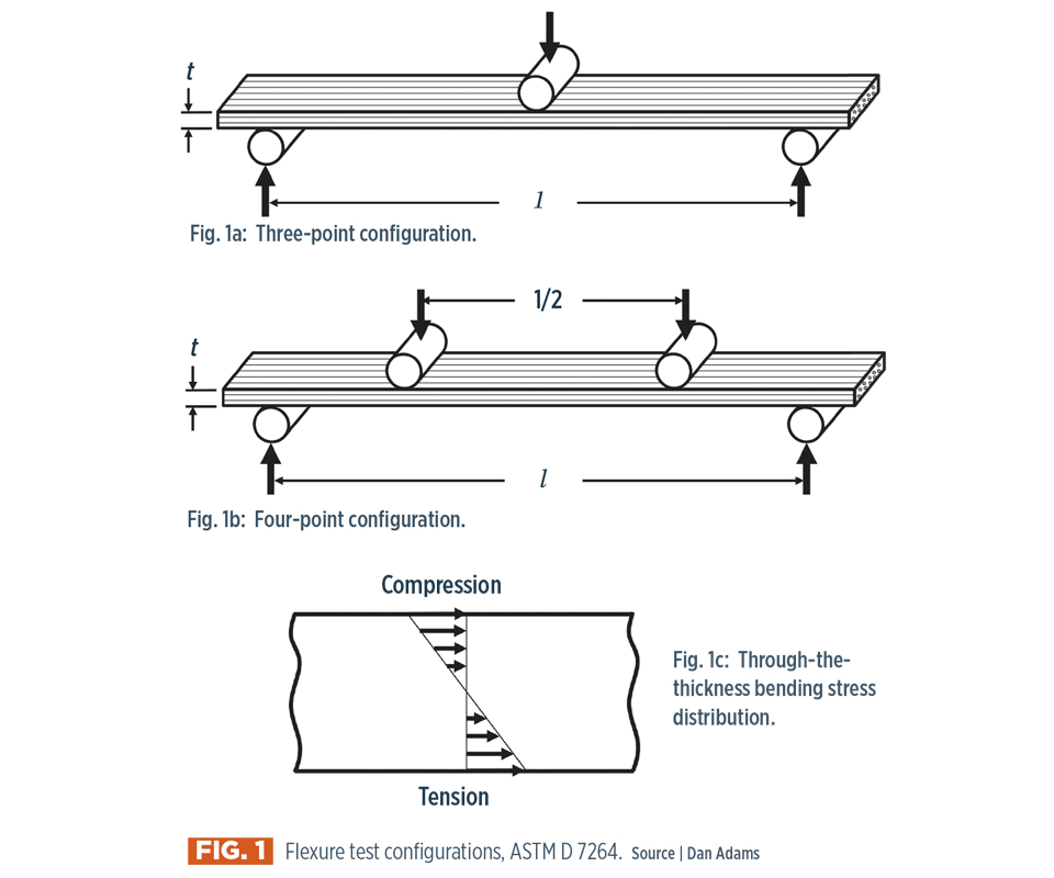
Fig. 1: Flexure test configurations, ASTM D 7264.
Source: Dan Adams
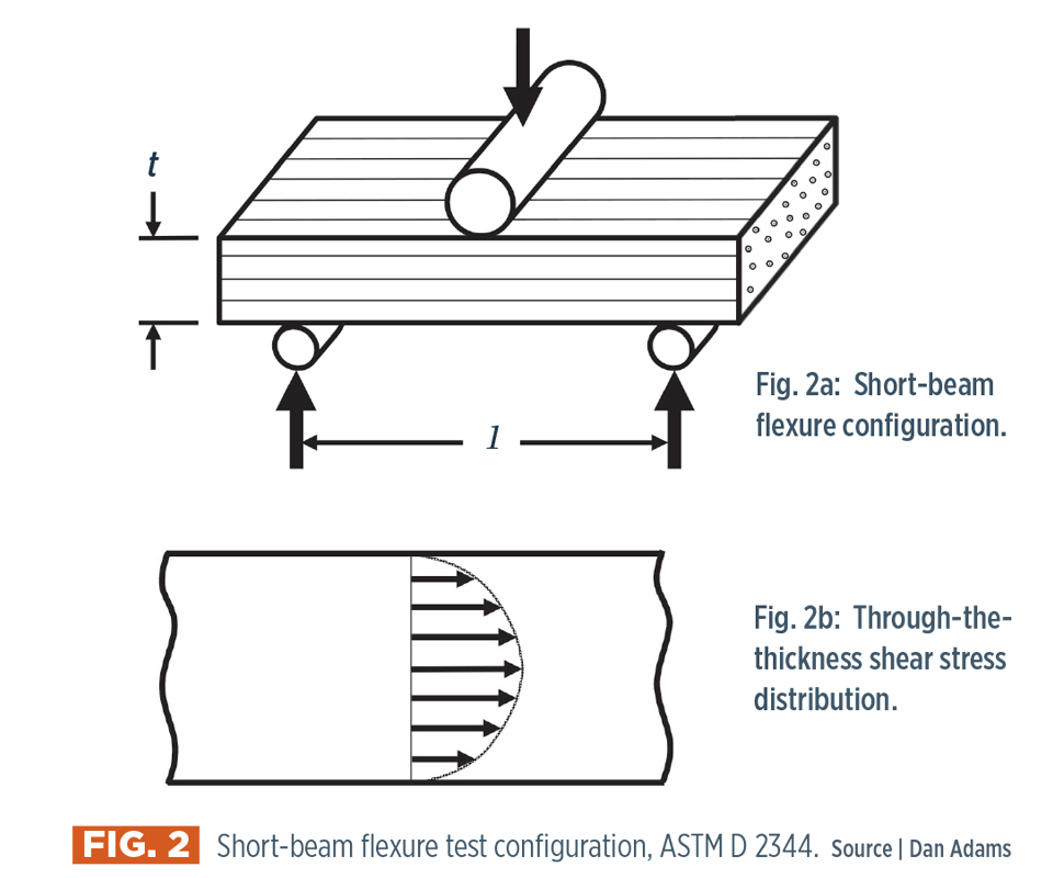
Fig. 2: Short-beam flexure configuration, ASTMD2344.
Source: Dan Adams
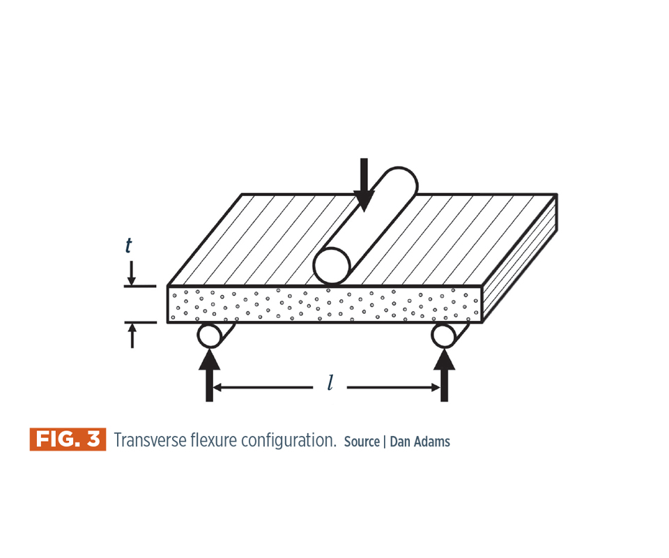
Fig. 3: Transverse flexure configuration.
Source: Dan Adams


Because composite structures are subjected to flexural loading in typical applications, it is not surprising that flexure testing of composites is commonly performed. Flexure testing is among the simplest of the test types to perform, yet the state of stress and failure modes produced within a flexure test specimen are among the most complex. Under both three-point and four-point flexural loading, the tensile, compressive and shear stresses that are produced vary along the length and through the thickness of the specimen.
Adding to the complexity, fiber-reinforced composites typically have different tensile and compressive strengths, as well as strength properties that vary greatly with fiber orientation. Depending on the span length as well as the material orientation of the specimen during a test, either a tensile, compressive or shear failure might be produced under flexural loading. In this column, we explore the conditions under which each of these failure types is produced, and the possibility of estimating certain strength properties of composite materials using flexure testing.


For starters, we consider the most common type of flexure test performed, in which the specimen is designed to fail due to bending stresses. For composite specimens, ASTM D 72641 specifies the span-to-thickness ratio, l/t, to be 32:1 for both three-point and four-point loading (Fig. 1). For four-point loading, the inner loading span is specified as being one-half of the outer span length (Fig. 1b).
The most important difference between these two loading configurations is the length of the region of maximum bending stress. Three-point loading produces maximum bending stress only at the central cross section located below the central loading cylinder. Four-point loading produces the maximum bending stress within the entire inner loading span. In both loading configurations, the relatively long span length produces maximum bending stresses along the top and bottom specimen surfaces (Fig. 1c), which are large relative to the maximum shear stress produced at the mid-thickness of the specimen. As a result, specimen failure typically is produced along either the top or bottom surface due to the maximum compressive or tensile stress, respectively. Note that these maximum stresses are equal in magnitude, and, thus, the failure mode and location depends on the relative magnitudes of the tensile and compressive strengths of the material that is undergoing testing.
For composite specimens in which the outer layers have reinforcing fibers oriented in the specimen’s length direction (0° orientation), compression failure typically occurs because the compressive strength is lower than the tensile strength. In ASTM D 7264, the measured strength property is referred to as the flexural strength, defined as the maximum stress at the outer surface of the specimen corresponding to the peak applied force. Although the topic is not discussed in the standard, this measured flexural strength is not considered a material property of the composite due both to the nonuniformity of the stress state and to the difference in volume in which the maximum stress is produced. In general, measured values of flexural strength can differ by 10-20% from the compression strength, measured using a standardized composite compression test method. However, as I noted in my July 2015 column, standardized compression tests are among the most difficult to perform properly for composite materials. As a result, the use of measured flexural strengths to provide an estimate of the 0° compression strength of a composite material, or to compare the compression performance of composite materials, is a somewhat common and, I and others believe, useful practice.
Consider next the case where the span-to-thickness ratio of the flexure specimen, l/t, is intentionally relatively small (Fig. 2a). For such short-beam flexure testing the bending stresses produced in the specimen are reduced, and thus the shear stresses in the flexure specimen are of greater significance. Under three-point loading, these shear stresses do not vary across the span length but do vary parabolically through the thickness as shown in Fig. 2b.
For composites, the corresponding interlaminar shear strength is small relative to the 0° tensile and compressive strengths. As a result, these shear stresses in the central region of the specimen thickness will produce an interlaminar shear failure. ASTM D 23442 specifies for short-beam flexure testing the use of three-point loading and a span-to-thickness ratio, l/t, of 4. The short-beam strength is calculated as the maximum shear stress produced at the mid-thickness of the specimen at failure. The absence of the word shear in the standard’s title and in any reference to the calculated strength value are evidence of the resistance to considering the measured strength value from this test method as a material property. Nonetheless, the short-beam strength measured using ASTM D 2344 is considered by many to be a useful estimate of the interlaminar shear strength of composites. Further, the ease with which the test can be performed has led to its common use for comparative testing of candidate composite materials.
Finally, we consider the case of a unidirectional composite flexure specimen with the fiber direction oriented along the specimen’s width (90° orientation) as shown in Fig. 3. When properly designed, this flexural test configuration may be used to estimate the transverse tensile strength of composite materials.
Because fiber-reinforced polymers have relatively low tensile and compressive strengths in the transverse (90°) direction, the bending stresses produced under flexural loading will cause failure prior to a shear failure, as they do in the short-beam test discussed above. Even with the relatively short span-to-thickness ratio, l/t, of 4 used in the short-beam test, the bending stresses produced will lead to transverse tensile failure, because the transverse tensile strength typically is lower than the transverse compression strength. Unlike the previous two flexural loading configurations, however, the transverse flexure test has neither been standardized nor received widespread attention. Previous studies3,4 have shown that measured strength values from this test configuration are higher than those obtained from the more traditional transverse tensile test of a 90° specimen, due to the relatively small material volume subjected to the maximum tensile stress. Thus, like the first two flexure test configurations, the transverse flexure test is a useful method for obtaining an estimate of a composite’s strength property even though the measured value might not be accepted as a true material property.
References
1ASTM D 7264/D 7264M-15, “Standard Test Method for Flexural Properties of Polymer Matrix Composite Materials,” ASTM International (W. Conshohocken, PA, US), 2015 (first issued in 2006).
2ASTM D 2344/D 2344M-16, “Standard Test Method for Short-Beam Strength of Polymer Matrix Composite Materials and Their Laminates,” ASTM International (W. Conshohocken, PA, US), 2016 (first issued in 1965).
3D.F. Adams, T.R. King, and D.M. Blackketter, “Evaluation of the Transverse Flexure Test Method for Composite Materials,” Composites Science and Technology, Vol. 39, No. 4, 1990, pp. 341-353.
4T.K. O’Brien, A.D. Chawan, K. DeMarco, and I. Paris, “Influence of Specimen Configuration and Size on Composite Transverse Tensile Strength and Scatter Measured Through Flexure Testing, Journal of Composites Technology & Research, Vol. 25, No. 1, 2003, pp. 3-21.


Related Content

Measuring ply-wise deformation during consolidation using embedded sensors
Strip-type shape sensor method claims real-time measurement of ply-wise deformation.
Read More
Notched testing of sandwich composites: The sandwich open-hole flexure test
A second new test method has been standardized by ASTM for determining notch sensitivity of sandwich composites.
Read More
Composite test methods (and specifications) for fiber-reinforced concrete structures
While initially focused on transitioning existing standards published by the American Concrete Institute, the relatively new ASTM Subcommittee D30.10 is developing new standardized test methods and material specifications for FRP composites.
Read More
Interlaminar tensile testing of composites: An update
New test method developments for measuring interlaminar tensile strength address difficulties associated with the ASTM D6415 curved beam flexure and ASTM D7291 flatwise tensile tests.
Read MoreRead Next

VIDEO: High-volume processing for fiberglass components
Cannon Ergos, a company specializing in high-ton presses and equipment for composites fabrication and plastics processing, displayed automotive and industrial components at CAMX 2024.
Read More
Developing bonded composite repair for ships, offshore units
Bureau Veritas and industry partners issue guidelines and pave the way for certification via StrengthBond Offshore project.
Read More
All-recycled, needle-punched nonwoven CFRP slashes carbon footprint of Formula 2 seat
Dallara and Tenowo collaborate to produce a race-ready Formula 2 seat using recycled carbon fiber, reducing CO2 emissions by 97.5% compared to virgin materials.
Read More