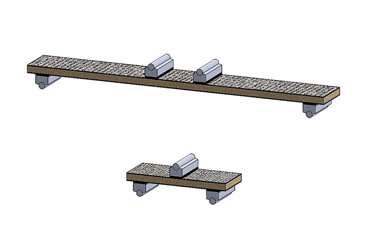
Fig 1. Specimen configurations used in sandwich composite flexure testing. 1a (top) is a long beam flexure configuration (ASTM D7249), and 1b. (bottom) depicts a short beam flexure configuration (ASTM C393). Source | Dan Adams
Sandwich composites consist of thin composite facesheets bonded to a relatively thick, low-density core. The use of the core to separate the two stiff and strong composite facesheets produces composite sandwich structures that are especially well-suited for flexural loading. Under such loading, the facesheets are subjected to tensile and compressive stresses associated with bending, whereas the central core is subjected primarily to shear stresses. Therefore sandwich composites can experience facesheet or core failures under flexural loading, and test methods have been developed to assess these two types of failures. The primary differences between these two types of flexure tests is the sandwich beam specimen’s support span length, long beam versus short beam, and the loading configuration, four-point versus three-point loading.
To produce facesheet failure in composite sandwich beam specimens and thereby determine the facesheet ultimate strength, relatively long span lengths and four-point loading configurations are used (Fig. 1a). ASTM D72491, the long beam flexure test method for sandwich composites, specifies a 76-millimeter wide and 600-millimeter long standard specimen. A 560-millimeter support span length coupled with a relatively short 100-millimeter loading span length is specified as the standard loading configuration. This configuration is intended to maximize the bending stresses in the facesheets while minimizing the shear stresses within the core. However, this standard configuration is intended for use only when the specimen design equations, provided in the ASTM standard, indicate that facesheet failure will be produced. Otherwise, changes in the support and loading span lengths are required to achieve the desired facesheet failure. Note that failure of the upper compression-loaded facesheet is expected, as the compression strength is lower than the tension strength for most composite materials. Additionally, ASTM D7249 provides a useful rule of thumb for specimen design: the support span length should be at least 20 times greater than the sandwich thickness. An additional concern is localized facesheet damage or core crushing occurring at the load introduction points. To address this concern, the ASTM test method specifies using 25-millimeter wide pivoting loading flats to help distribute the force over a larger area (Fig. 2). Additionally, the use of 3-millimeter thick rubber pressure pads placed onto the steel flats is recommended to further reduce stress concentrations.
To produce core failure in composite sandwich beam specimens under flexure loading, relatively short span lengths and a three-point loading configuration are used (Fig. 1b). ASTM C3932, the short beam flexure test method for sandwich composites, specifies a 76-millimeter-wide and 200-millimeter-long standard specimen. The relatively short 150-millimeter support span, coupled with the single central loading point, minimizes the bending stresses in the facesheets and produces core shear failure. The same pivoting loading flats and rubber pressure pads specified in the long beam flexure test are used to prevent failure at the loading points. In fact, the same adjustable test fixture used to perform long beam flexure tests (Fig. 2) may be used to perform short beam flexure tests by placing one loading head at the midpoint and removing the other. Similar to the long beam flexure test, ASTM C393 provides specimen design equations for use in producing core shear failure prior to facesheet failure and localized core compression failure at the central loading point. Note that both core shear and core-to-facesheet bond failures are considered acceptable failure modes.
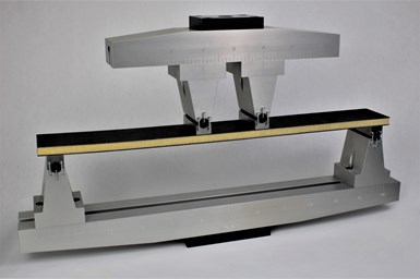
Fig 2. Long beam flexure test fixture and sandwich composite specimen. Source | Wyoming Test Fixtures, Inc.
Those reading ASTM C393 may also note that four-point loading configurations are included in the test method, even though they are not recommended for short beam flexure testing to determine the core shear ultimate strength. The reason? Prior to 2006, ASTM C393 was the only sandwich flexural test method for sandwich composites. As a result, this earlier version of the standard included short beam and long beam sandwich specimens and three- and four-point loading. Additionally, minimal guidance was provided on specimen design and test configuration to produce the desired failure mode. In 2006 when ASTM D7249 was standardized for long beam flexure testing, ASTM C393 was rewritten to focus only on short beam flexure testing. However, the four-point loading configuration was retained in the standard for “historical continuity” with previous versions of this test method3.
Additionally, in 2006, ASTM D72504 was standardized for use in determining the stiffness properties of sandwich composites using test results from the long beam and short beam flexure tests. This standard practice describes the procedure and presents equations for calculating the sandwich flexural and shear stiffness as well as the core shear modulus. Force versus deflection and/or strain data is required from at least one long beam (ASTM D7249) and one short beam (ASTM C393) flexure test configuration. These stiffness properties are determined by simultaneous solution of the deflection equations for each test configuration.
Having summarized the two standardized flexural loading configurations used for sandwich composites, I’ll conclude by pointing out their similarities with those currently used for flexure testing of composite laminates, or solid composites. As in the case of sandwich composites, the two standardized flexure test methods also fall into the categories of long beam and short beam flexure tests. The solid composite long beam flexure test, ASTM 72645, permits the use of three-point and four-point loading, with the choice left to the user. A span-to-thickness ratio of 32:1 is recommended for both loading configurations, which produce maximum bending stresses along the outer specimen surfaces. Specimen failure typically is produced at the top of the specimen due to the maximum compression stress, referred to as the flexural strength of the composite laminate. In contrast, the short beam flexure test for solid composites, ASTM 23446, uses a span-to-thickness ratio of only 4:1 and three-point loading. This test method is used to determine the short beam strength, defined as the maximum shear stress produced at the mid-thickness of the specimen at failure. As discussed in my October 2017 column, neither the measured flexural strength nor the short beam strengths measured using these tests are considered material properties of the composite material due to the nonuniformity of the stress state and the volume in which the maximum stress is produced. Under some conditions, however, these measured quantities may be used as material property estimates.
References
1ASTM D7249 / D7249M-20, “Standard Test Method for Facesheet Properties of Sandwich Constructions by Long Beam Flexure,” ASTM International (W. Conshohocken, PA, US), 2020 (first issued in 2006).
2ASTM C393 / C393M-16, “Standard Test Method for Core Shear Properties of Sandwich Constructions by Beam Flexure,” ASTM International (W. Conshohocken, PA, US), 2016 (first issued in 1957).
3Sawicki, A.J., “Development of Standard Test Methods for Sandwich Composites Under ASTM Committee D30,” proceedings of the 2009 International Conference on Composite Materials, ICCM17, Edinburgh, UK, July 2009.
4ASTM D7250 / D7250M-16, “Standard Practice for Determining Sandwich Beam Flexural and Shear Stiffness,” ASTM International (W. Conshohocken, PA, US), 2016 (first issued in 2006).
5ASTM D 7264 / D 7264M-15, “Standard Test Method for Flexural Properties of Polymer Matrix Composite Materials,” ASTM International (W. Conshohocken, PA, US), 2015 (first issued in 2006).
6ASTM D 2344 / D 2344M-16, “Standard Test Method for Short-Beam Strength of Polymer Matrix Composite Materials and Their Laminates,” ASTM International (W. Conshohocken, PA, US), 2016 (first issued in 1965).
Related Content
ASCEND program update: Designing next-gen, high-rate auto and aerospace composites
GKN Aerospace, McLaren Automotive and U.K.-based partners share goals and progress aiming at high-rate, Industry 4.0-enabled, sustainable materials and processes.
Read MoreComposite sidewall cover expands options for fire-safe rail components
R&D project by CG Rail explores use of carbon fiber-reinforced thermoplastics and recycled manufacturing scrap to meet fire safety, weight and volume targets.
Read MorePlant tour: BeSpline/Addcomp, Sherbrooke, QC, Canada
Composites automation specialist increases access to next-gen technologies, including novel AFP systems and unique 3D parts using adaptive molds.
Read MoreATLAM combines composite tape laying, large-scale thermoplastic 3D printing in one printhead
CEAD, GKN Aerospace Deutschland and TU Munich enable additive manufacturing of large composite tools and parts with low CTE and high mechanical properties.
Read MoreRead Next
The Single Cantilever Beam test for sandwich composites
After several years of research and development, the Single Cantilever Beam test method is in the process of standardization within ASTM's Committee D30 on Composites.
Read MorePlant tour: Daher Shap’in TechCenter and composites production plant, Saint-Aignan-de-Grandlieu, France
Co-located R&D and production advance OOA thermosets, thermoplastics, welding, recycling and digital technologies for faster processing and certification of lighter, more sustainable composites.
Read MoreAll-recycled, needle-punched nonwoven CFRP slashes carbon footprint of Formula 2 seat
Dallara and Tenowo collaborate to produce a race-ready Formula 2 seat using recycled carbon fiber, reducing CO2 emissions by 97.5% compared to virgin materials.
Read More


