


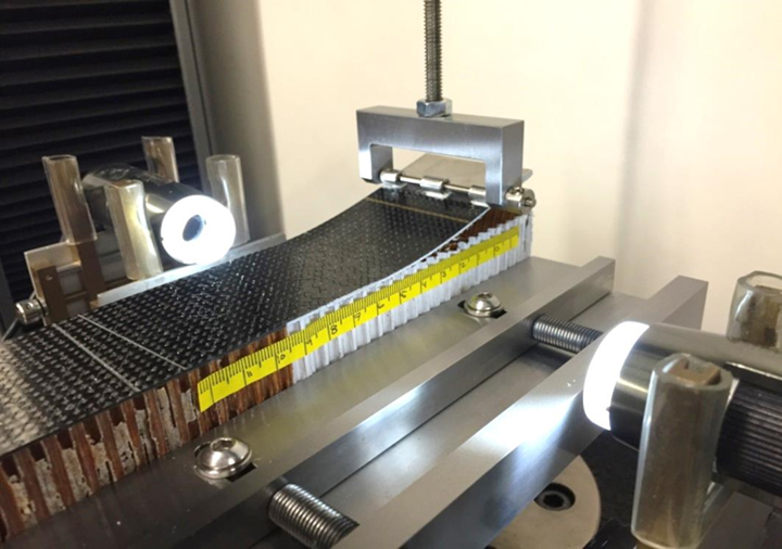
Fig. 1. Single Cantilever Beam (SCB) test configuration. Source | Wyoming Test Fixtures
In recent years, there’s been increasing interest in the development and standardization of new test methods for sandwich composites, including fracture mechanics, notch sensitivity and damage tolerance tests. This recent trend for sandwich composites resembles the period of development (and later standardization) of the same test methods for polymer matrix composites (PMC) in the 1980s and 1990s. In both cases, these developments were driven by new applications for which these properties were important design considerations. In this column, we focus on a Mode I fracture mechanics test for sandwich composites that’s approaching ASTM standardization — the Single Cantilever Beam (SCB) test.
For starters, fracture mechanics test methods are used to measure a material’s resistance to growth of an existing crack. For PMCs, the Mode I fracture mechanics test method is the Double Cantilever Beam (DCB) test, standardized as ASTM D55281 in 1994. This test is used to measure the resistance to growth, or fracture toughness, for an existing delamination within a unidirectional laminate under an opening-mode (Mode I) loading.


Similarly for sandwich composites, the SCB test is used to measure the Mode I fracture toughness of an existing disbond in the facesheet/core interface region. A vertical tensile force is applied using a piano hinge or loading block that’s bonded to the end of the upper facesheet (Fig. 1). The debonded end of the upper facesheet functions as a cantilever beam, and thus the name — single cantilever beam test. The lower facesheet of the sandwich specimen is secured to the base fixture using an edge-clamping mechanism.
Unlike the DCB test, in which the measured fracture toughness is considered a material property of the PMC, the fracture toughness produced using the SCB test is considered a structural property. The reason? The measured fracture toughness depends on the sandwich configuration tested — including the facesheet material and thickness, the core material, the adhesive and the manufacturing method. Additionally, changes to the sandwich configuration may result in the disbond propagating at different through-thickness locations within the facesheet/core interface region.
This concept of a structural property has been observed when testing a series of SCB test specimens from the same sandwich panel but with different facesheet thicknesses, produced by bonding two thicknesses of glass/epoxy doublers to the outer surface of the facesheet prior to testing (Fig. 2.) As the total thickness of the facesheet (and thus the flexural rigidity) increases, the measured Mode I fracture toughness, GIc, increases. This increase is associated with the disbond migrating away from the adhesive layer adjacent to the facesheet and into the neighboring core material — in this case, a Nomex honeycomb. Detailed finite element analyses show that shear stresses exist in front of the crack tip, producing a small Mode II (shearing) component of the fracture toughness. While small relative to the through-thickness tensile stress, these shear stresses change in sign (positive or negative) and in magnitude depending on distance from the facesheet, and produce the observed differences in the measured fracture toughness and the through-thickness disbond locations. Due to this small Mode II component that may be present, the SCB test is referred to as a Mode I-dominant test.
Fig. 2 Through-thickness disbond location and resulting GIc values for increasing facesheet thickness. Source: Dan Adams
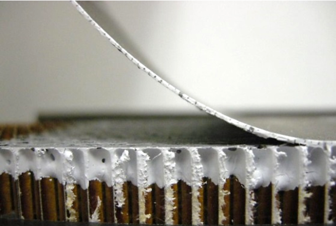
A.
Facesheet only
GIc ≈ 0.6 N-mm/mm2
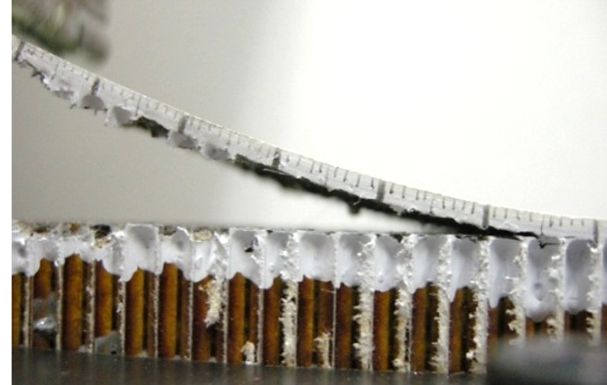
B.
Facesheet + 0.6 mm doubler
GIc ≈ 1.2 N-mm/mm2
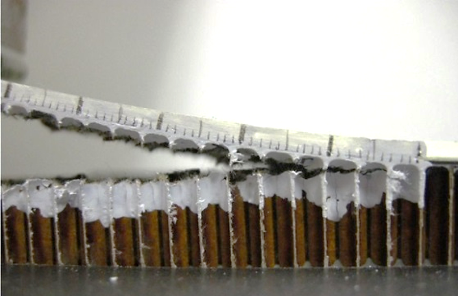
C.
Facesheet + 1.6 mm doubler
GIc ≈ 1.8 N-mm/mm2
Similar to the DCB test for unidirectional laminates, both initiation and propagation fracture toughness properties may be obtained using the same SCB test specimen. The initiation fracture toughness is a measure of the resistance to initial growth of a disbond with a prescribed crack front and at a designated through-thickness location. When used to investigate initial disbond growth from a sharp crack tip, an extremely thin (~10 microns) non-adhesive PTFE film is inserted into the facesheet/core bondline during sandwich panel manufacturing. However, other types of crack fronts may be of interest, such as those produced by foreign object debris (FOD) present at the facesheet/core interface. When performing the test, force and displacement values are recorded at multiple disbond lengths until the disbond has propagated 10-15 millimeters. The initiation fracture toughness is calculated using a modified beam theory method similar to that used in the ASTM D5528 DCB test method. Since linear elastic behavior is assumed when calculating the initiation values of GIc, a suitable initial disbond length must be determined to avoid both large rotations and flexural failure of the disbonded facesheet during testing2.
The propagation fracture toughness is associated with the resistance to growth of a naturally propagated disbond that has stabilized at its preferred through-thickness location. Thus, prior to measurement, an initial disbond must be propagated a moderate distance, typically 10-15 millimeters, to allow for the through-thickness location of the natural crack tip to stabilize. If initiation fracture toughness testing has been performed, the resulting 10-15-millimeter disbond propagation is typically sufficient. Otherwise, the initial disbond may be produced using a razor blade or fine-tooth sawblade, keeping as close to the facesheet/core interface as possible. A 10-15-millimeter length of disbond propagation is typically sufficient to produce the through-thickness stabilized, naturally propagated disbond.
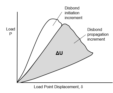
Fig. 3. Area method for propagation fracture toughness determination. Source | Dan Adams
The propagation fracture toughness is calculated using an area method, in which the enclosed area produced in the applied force versus crosshead displacement plot during loading and unloading is used. Since this method does not require linear elastic behavior, large rotations of the disbonded facesheet are permissible. The specimen is loaded at a constant crosshead rate and the force and the displacement values are recorded at regular intervals so that the loading and unloading curves can be properly generated (Fig. 3). The disbond is propagated 30 to 40 millimeters, and the test is paused to mark the final position of the disbond tip prior to unloading. The propagation fracture toughness is calculated as
,
where ΔU is the loss in strain energy corresponding to the area of disbond growth, ΔA. The value of ΔU is calculated as the shaded area shown in Fig. 3 using a computer-generated numerical integration method such as the trapezoidal method.
After several years of research and development, the Single Cantilever Beam test method is in the process of standardization within ASTM’s Committee D30 on Composites. Further information may be obtained by contacting the author.


Related Content

Composite sidewall cover expands options for fire-safe rail components
R&D project by CG Rail explores use of carbon fiber-reinforced thermoplastics and recycled manufacturing scrap to meet fire safety, weight and volume targets.
Read More
The basics of composite drawing interpretation
Knowing the fundamentals for reading drawings — including master ply tables, ply definition diagrams and more — lays a foundation for proper composite design evaluation.
Read More
Improving carbon fiber SMC simulation for aerospace parts
Simutence and Engenuity demonstrate a virtual process chain enabling evaluation of process-induced fiber orientations for improved structural simulation and failure load prediction of a composite wing rib.
Read More
Active core molding: A new way to make composite parts
Koridion expandable material is combined with induction-heated molds to make high-quality, complex-shaped parts in minutes with 40% less material and 90% less energy, unlocking new possibilities in design and production.
Read MoreRead Next

Fracture mechanics test methods for sandwich composites
HPC's testing guru, Dr. Donald F. Adams (Wyoming Test Fixtures, Salt Lake City, Utah), surveys the available fracture mechanics test methods for sandwich panels.
Read More
“Structured air” TPS safeguards composite structures
Powered by an 85% air/15% pure polyimide aerogel, Blueshift’s novel material system protects structures during transient thermal events from -200°C to beyond 2400°C for rockets, battery boxes and more.
Read More
VIDEO: High-volume processing for fiberglass components
Cannon Ergos, a company specializing in high-ton presses and equipment for composites fabrication and plastics processing, displayed automotive and industrial components at CAMX 2024.
Read More