
Impact testing of composite materials
Dr. Donald F. Adams (Wyoming Test Fixtures (Salt Lake City, Utah) discusses the methods for impact testing of composites.
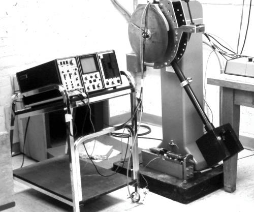
Fig. 1: A pendulum-type impact test apparatus. Source: Don Adams
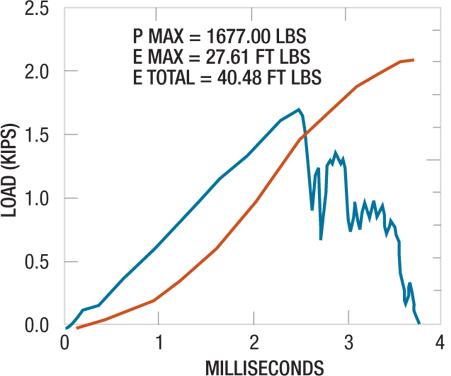
Fig. 2: A typical impact force vs. time plot for a composite material. Source: Don Adams
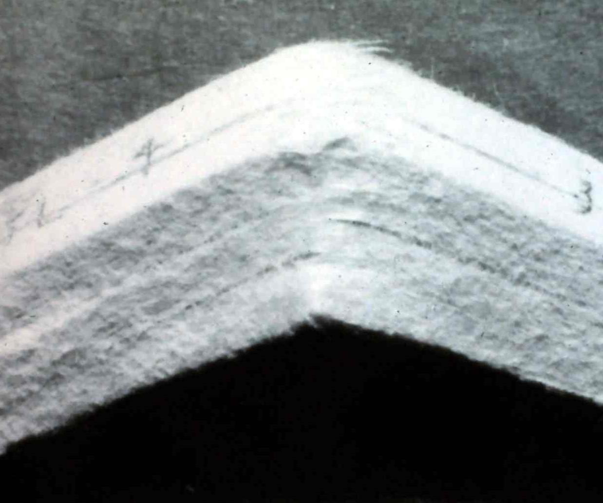
Fig. 3: Failure of a Kevlar/epoxy unidirectional composite Charpy impact specimen. Source: Don Adams


The impact response of composite materials was of only minor interest prior to the introduction of carbon fiber in the mid-1960s. Before that time, the composites in use were primarily reinforced with glass fibers, which performed well under impact loads. This soon proved not to be true for carbon fibers, which are relatively brittle. But since their static strength and stiffness properties were very attractive, development of carbon fiber reinforcements for structural applications continued. However, by the early 1970s the need to characterize the impact response of carbon fiber composites was evident.
The first attempts to study the impact response of composites — not only those reinforced with carbon fibers but others, as well — focused on the use of the Charpy impact test method. This test was originally developed for metals1 and was extended later to unreinforced plastics.2 Given that history, the Charpy test appeared to be a logical choice for composites.


The Charpy test subjects a small beam, with a 55-mm/2.17-inch long and 10-mm/0.39-inch square cross- section, to a three-point flexural impact loading induced by a swinging pendulum (such as that shown in Fig. 1). The test specimen contains a 45° included-angle notch, which is 2-mm/0.079-inch deep, on the tensile side to induce failure at that point.
When the test method was originally developed, the amount of energy absorbed by the specimen was simply defined as the change in potential energy related to the difference in the height of the swinging pendulum before it was released and the maximum height it reached as it passed through the specimen after impact. Sufficient energy was delivered to the specimen to ensure that it was completely fractured during the impact process.
By the time they were used to test composites, pendulum-type impact testers were being instrumented with a piezoelectric crystal load cell in the impact head, which made it possible to generate a force vs. time curve. By integrating the area under this curve, the absorbed energy as a function of time could be determined and plotted (see an example in Fig. 2).
The problem with Charpy impact testing is that, unlike for metals and plastics where a simple tensile failure could be induced at the notch root, the failure mode of composite materials was often complex. An example is shown in Fig. 3 for a unidirectional Kevlar/epoxy composite. All three basic failure modes — tension, compression and shear — are exhibited in the same specimen. That is, the mode of failure of the composite is inconsistent, and thus it is difficult to relate the measured absorbed energy of the Charpy specimen to that of an actual structural component. Thus, after considerable research, Charpy impact testing of composites was abandoned.
Attempts were then made to develop a pure tensile impact test.3 The pendulum-type impact test machine was retained because it is available in many laboratories. Fixturing was developed in which the pendulum, passing over one end of the specimen that was anchored to the base of the testing machine, struck projections attached to the other end, subjecting the specimen to tension. The apparatus is shown mounted on the base of the impact tester in Fig. 1. This test method was to be followed by the development of similar compression- and shear-impact test methods. But after much careful development it was determined that the impact stress/strain responses of the many tested composites were little different than their static responses, thus negating the value of tensile impact testing. As a result, the concept of developing pure stress-state impact loading tests also was abandoned.
Because a primary concern is potential damage to composite structures induced by low-velocity impact, such as might occur due to a tool drop on an aircraft wingskin or an automobile component bumping a stationary object, striking a flat plate with a falling weight was subsequently adopted as the impact test method of choice. Much development work was conducted throughout the 1980s, and corresponding test equipment was developed.4 This typically consisted of an instrumented impact drop tower and associated data-reduction equipment, and today it remains the impact test method of choice for composite materials. Typically, a plate on the order of 150-mm/6-inches square is simply supported around its four sides and then is impacted at its center. The impacting tup is typically hemispherical and is on the order of 15 mm/0.60 inch in diameter. The delivered level of impact energy is selectable. Therefore, test technicians have the option to ensure full penetration, in which case the results of interest are the maximum force and the energy absorbed to maximum force, and/or the total energy absorbed during the full penetration process. Alternatively, the test panel may be subjected to a prescribed level of impact energy, selected to induce local damage without penetration. In fact, when the intent is to induce and then detect damage that may not be evident by visual inspection of a structure, surface damage may be barely visible. In this case, an ultrasonic C-scan unit is used to quantify the extent of internal damage.
To determine strength degradation, the postimpact panel can be subjected to a static load. Compressive strength is particularly susceptible to local material degradation. To gauge this, a compression after impact (CAI) test is used. This is the basis of ASTM D7137,5 which uses a 100-mm by 150-mm (4-inch by 6-inch) drop-weight impacted specimen6 subjected to a uniform in-plane compressive force along its 100-mm/4-inch long edges. The specimen is simply supported along all four edges to inhibit buckling.
As a result of the various developments cited in this article, instrumented impact testing of composite material plates is now relatively well developed, generally accepted and widely used.
Wyoming Test Fixtures Inc.
References
1ASTM E23-07, “Notched Bar Impact Testing of Metallic Materials,” ASTM International (W. Conshohocken, Pa.), 2007 (originally published 1933).
2ASTM D6110-10, “Determining the Charpy Impact Resistance of Notched Specimens of Plastics,” ASTM International (W. Conshohocken, Pa.), 2010.
3J. D. Winkel and D. F. Adams, “Instrumented Drop Weight Impact Testing of Cross-Ply and Fabric Composites,” Composites, Vol. 16, No. 4, October 1985, pp. 268-278.
4D. F. Adams and L. G. Adams, “A Tensile Impact Apparatus for Composite Materials,” Experimental Mechanics, Vol. 29, No. 4, December 1989, pp. 466-473.
5ASTM D7137-07, “Compressive Residual Strength Properties of Damaged Polymer Matrix Composite Plates,” ASTM International (W. Conshohocken, Pa.), 2007 (originally published 2005).
6ASTM D7136-07, “Measuring the Damage Resistance of a Fiber-Reinforced Polymer Matrix Composite to a Drop-Weight Impact Event,” ASTM International (W. Conshohocken, Pa.), 2007 (originally published 2005).


Related Content

Automated robotic NDT enhances capabilities for composites
Kineco Kaman Composites India uses a bespoke Fill Accubot ultrasonic testing system to boost inspection efficiency and productivity.
Read More
3D-printed CFRP tools for serial production of composite landing flaps
GKN Aerospace Munich and CEAD develop printed tooling with short and continuous fiber that reduces cost and increases sustainability for composites production.
Read More
ATLAM combines composite tape laying, large-scale thermoplastic 3D printing in one printhead
CEAD, GKN Aerospace Deutschland and TU Munich enable additive manufacturing of large composite tools and parts with low CTE and high mechanical properties.
Read More
Nine factors to consider when designing composites cure tooling
Gary Bond discusses the common pitfalls and compromises when designing good cure tooling and their holistic significance for a robust composite production process.
Read MoreRead Next

“Structured air” TPS safeguards composite structures
Powered by an 85% air/15% pure polyimide aerogel, Blueshift’s novel material system protects structures during transient thermal events from -200°C to beyond 2400°C for rockets, battery boxes and more.
Read More
Developing bonded composite repair for ships, offshore units
Bureau Veritas and industry partners issue guidelines and pave the way for certification via StrengthBond Offshore project.
Read More
Plant tour: Daher Shap’in TechCenter and composites production plant, Saint-Aignan-de-Grandlieu, France
Co-located R&D and production advance OOA thermosets, thermoplastics, welding, recycling and digital technologies for faster processing and certification of lighter, more sustainable composites.
Read More