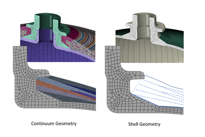
Fig 1. 2D and 3D continuum and shell meshes of WoundSim benchmark. Photo Credit, all images: QustomApps
The filament winding process has gained broad support among a wide range of applications, from rocket propellant tanks and automobile hydrogen storage tanks to scuba and firefighting equipment. In particular, the high stiffness-to-weight ratio of these composite-overwrapped pressure vessels (COPVs) makes them ideal for such uses. The analyses of pressure vessels, however, can be a time-consuming and difficult task using the off-the-shelf capabilities of commercial finite element codes such as Abaqus (Dassault Systèmes, Waltham, Mass., U.S.), and Ansys (Canonsburg, Pa., U.S.). Specialized tools are required to accurately predict the behavior of COPVs due to the continually varying layer thicknesses and fiber orientations.
When looking to improve upon traditional analysis procedures of COPVs, there are two areas that must be addressed. First, the geometry of the composite vessel must completely match that of the underlying liner. Second, equivalent materials properties must be computed that can accurately capture the material properties of the interwoven composite bands whose orientations are continually varying.
This article discusses the methodologies implemented in the WoundSim tool which has been developed specifically for the analysis of COPVs and to be tightly integrated with the commercial code Abaqus.
Continuum-based composite geometry
In most pressure vessels, the traditional shell approach cannot match the underlying liner geometry. Shell geometry is constructed by defining a line in 2D or a surface in 3D and extruding perpendicularly to the line or surface. This extrusion does not allow the shell geometry to wrap around discontinuities in the polar region such as that shown in Fig 1. To achieve this, continuum geometry must be created. WoundSim has been developed to generate either 2D or 3D continuum geometry that matches that of the liner.
Shell geometry is useful for analyses such as buckling of the liner or dynamic impact in which the contact occurs away from the polar boss. In these cases, the accuracy of the simulations in polar boss regions may not be important since the polar boss may not be involved in the impact and definitely not involved in the buckling of the liner. However, when designing a pressure vessel, the first consideration is that of burst pressure. Design standards typically require the cylinder stresses be about 20% higher than the stresses in polar boss regions, since the polar boss may become a dangerous projectile if the tank fails in that region. To accurately capture this requirement, continuum geometry matching the liner exactly is critical.
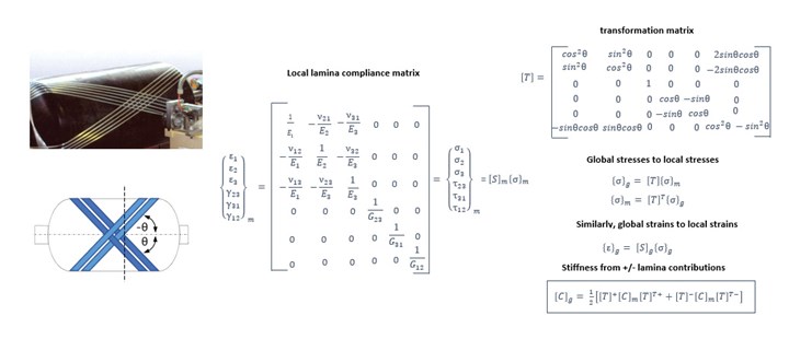
Fig 2. Transformation of local compliance to global compliance.
Smeared property approach
Many analyses of COPVs are performed using the standard composite layup approach available in commercial codes. This approach entails defining a layer at 10º, for example, and a second layer defined over the top of the first at -10º in order to model a single 10º helical layer. While this approach can often obtain reasonable results, it becomes less accurate as the layer approaches the region of the polar boss and as the pressure tanks become thicker. This is because the bands at the plus and minus directions become woven together as they are laid down and thus, on average, exist at the same position through the thickness of the layer. To mitigate this, WoundSim takes a more rigorous avenue toward approximating the composite properties of a layer via the smeared property approach.
The smeared property approach uses the local lamina properties of the band, which are known and provided by the user, and transforms them to a global coordinate system (Fig. 2). This operation, performed on properties in the plus and minus directions, results in an equivalent set of properties in the global coordinate system. This requires specialized user subroutines for the analysis and thus is not commonly used, even though it provides the most rigorous approach to approximate the material properties of a woven filament-wound composite.
Post-processing for smeared property approach
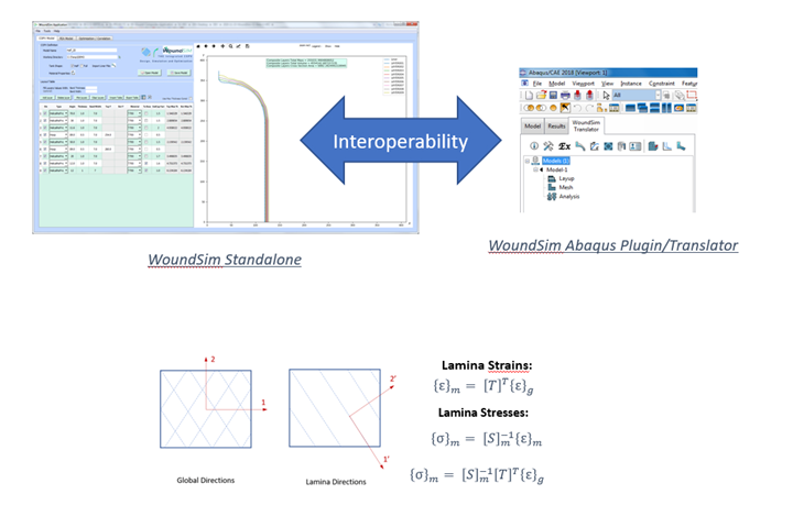
To determine the load-carrying capacity of the pressure vessel, the stresses and strains in the direction of the fibers must be computed. Failure criteria such as maximum stress/strain, Tsai-Wu, Tsai-Hill and others can be used, but are all based on the lamina stresses and strains in the fiber direction and transverse to the fiber direction. However, the smeared property approach computes properties in a global coordinate system, so those smeared stresses and strains must be converted to local stresses and strains through coordinate transformations and the compliance matrix of the lamina (Fig. 3).
WoundSim uses a Fortran user-subroutine to perform these calculations. A library is pre-built with the Fortran routine so the user does not need to have a Fortran compiler installed to run the analysis. The Fortran routine contains a UVARM subroutine which is an Abaqus subroutine available for computing user-defined output quantities.
Flexibility in modeling techniques
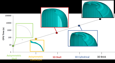
The design of composite pressure vessels usually requires that more than one type of analysis be performed on the vessel. Depending on the type of analysis, the geometry requirements may change. For example, if performing an optimization or design-of-experiments study in which hundreds or even thousands of analyses may be required, it is more practical to perform such procedures with axisymmetric models. These may consist of an axisymmetric shell or continuum elements that are computationally inexpensive; however, the analysis will be limited to axisymmetric loading such as pressurization or autofrettage loads. If non-axisymmetric loading is required — such as a simple bending analysis — then the user must graduate toward more computationally expensive elements, such as 3D shell, cylindrical elements.
For very generalized 3D behaviors, such as off-axis impact car-crash analyses, 3D continuum models will be required. Although the loading of the tank will often dictate the type of model geometry required, an important consideration is the dramatic effect the geometry type may have on the simulation run time. Figure 4 identifies geometry selection versus approximate run times, indicating the importance of having the ability to choose the geometry that is most appropriate for a given analysis.
Seismic changes are occurring in the way energy is used and stored. Composite pressure vessels are going to play a larger role in energy storage as the world converts to zero-emission technologies. Accurately predicting the behavior of composite pressure vessels, and thus ensuring their safe use, is a key concern for a wide range of companies developing next-generation energy and mobility/transport applications. Accurate modeling of pressure vessel geometry and rigorous, proven approximations for the material properties of the windings, will help ensure composite tanks are designed to the highest level of safety as they become more prevalent and play a more crucial role in our lives.
About the Author
Mike Shubert
Mike Shubert completed his BSc and MSc at the University of Colorado, Boulder in structural civil engineering with an emphasis on finite element analysis of composite material structures. After 13 years of developing Abaqus solvers at Hibbitt-Karlsson & Sorensen, he moved to the Irving, Texas, sales office, where he developed vertical applications for Abaqus including the Wound Composite Modeler, the Abaqus Welding Interface, the PCB Modeler and many others. He left Dassault Systèmes in 2019 and started QustomApps (Dallas, Texas) to develop high quality, easy-to-use applications within the Abaqus, Abaquas/CAE and Dassault Systèmes environments. info@qustomapps.com
About the Author
Amine Abichou
Amine Abichou has a Master’s degree in mechanical engineering from the engineering school of Paris “SupMeca.” He has 14 years of experience working in the field of mechanical engineering and numerical simulation for different industries: automotive (e.g., Mercedes Benz, Faurecia), oil and gas (Total SA, SAIPEM). He also worked for five years in Dassault Systèmes to become a certified advanced trainer and solution expert around Abaqus software and other Simulia products. In 2017, he founded S Vertical (Châtenay-Malabry, France) company and began development of WoundSim software to address the market of COPV design and manufacturing. amine.abichou@svertical.com
Related Content
Crashworthiness testing of composites: A building block approach, Part 2
Following the previously discussed coupon-level testing element, subcomponent and component testing are the next steps in designing crashworthy composite structures.
Read MoreComposite test methods (and specifications) for fiber-reinforced concrete structures
While initially focused on transitioning existing standards published by the American Concrete Institute, the relatively new ASTM Subcommittee D30.10 is developing new standardized test methods and material specifications for FRP composites.
Read MorePhotothermal tomography for locating, quantifying defects in composites
Years of infrared testing development result in thermography technology that is no longer just qualitative, but can define defect size and depth, making additional UT scans obsolete.
Read MoreInterlaminar tensile testing of composites: An update
New test method developments for measuring interlaminar tensile strength address difficulties associated with the ASTM D6415 curved beam flexure and ASTM D7291 flatwise tensile tests.
Read MoreRead Next
“Structured air” TPS safeguards composite structures
Powered by an 85% air/15% pure polyimide aerogel, Blueshift’s novel material system protects structures during transient thermal events from -200°C to beyond 2400°C for rockets, battery boxes and more.
Read MoreDeveloping bonded composite repair for ships, offshore units
Bureau Veritas and industry partners issue guidelines and pave the way for certification via StrengthBond Offshore project.
Read MoreVIDEO: High-volume processing for fiberglass components
Cannon Ergos, a company specializing in high-ton presses and equipment for composites fabrication and plastics processing, displayed automotive and industrial components at CAMX 2024.
Read More


