National Composites Center and Meggitt demonstrate linear dielectric sensor for liquid composites processing
Research at Cranfield University is further developed via RTM part trials in NCC’s Technology Pull-Through Program
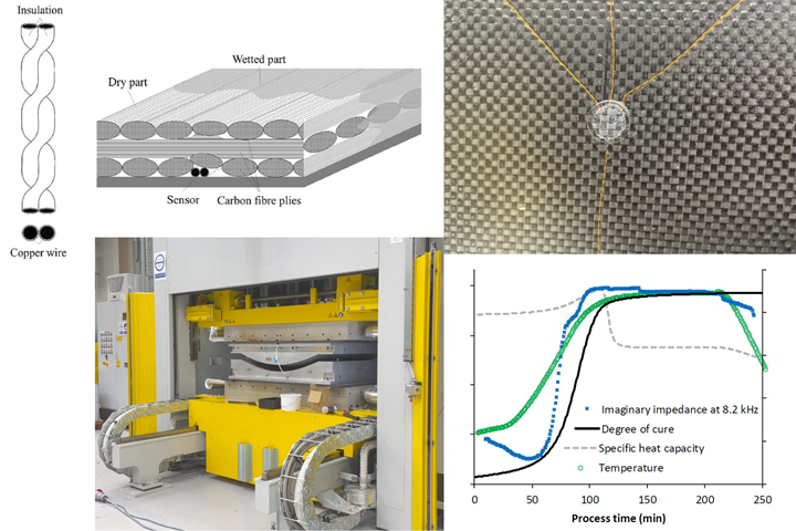
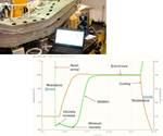
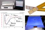
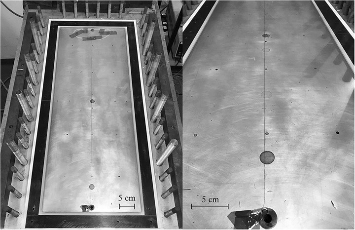
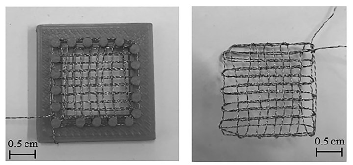
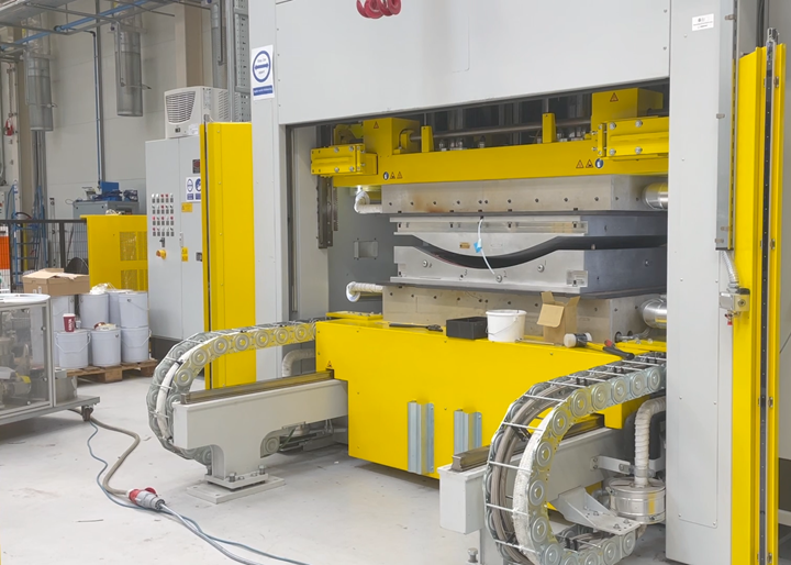
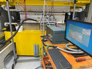
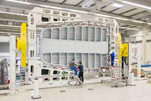
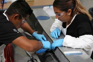
Cranfield University developed a linear dielectric sensor (top left) able to be used with CFRP parts (top right) to monitor both resin flow and resin cure (bottom right), demonstrated in RTM trials with the NCC (Bristol, U.K.) and aerostructures supplier Meggitt (bottom left). Photo Credit: Cranfield University, Meggitt, NCC.
This blog follows an NCC press release that CW published in January 2022, after which I interviewed the team involved. I also included their work in my upcoming March 2022 feature article on Sensors. Here, I give more details and images.
Note, the technology described here is based on dielectric sensors. As explained in my blogs “DC dielectric sensors for industrial composites production” and “Combining AC and DC dielectric sensors for cure monitoring of composites”, dielectric analysis (DEA) has been used for decades to monitor viscosity and cure state changes in thermoset and thermoplastic resins, adhesives and paints. DEA can be used to analyze cure in composites by applying a voltage between two electrodes placed in contact with the matrix resin and measuring the change in the resin’s dielectric properties. The voltage may be alternating current (AC) or direct current (DC), and the dielectric properties measured include a polymer’s resistance to ion flow (reported as resistivity) and capacitance (reported as permittivity). As explained in the above blogs, these measurements help to understand how the resin is moving and how it is changing, including its increase in viscosity and its glass transition through cure.
One noticeable difference in the dielectric sensor described in this blog, compared to the single-point dielectric sensors discussed in my previous blogs is that this sensor is linear, comprised of a continuous length of wire that senses along its whole length.
How did this project get started?
“Our first session for monitoring resin flow during resin transfer molding (RTM) was with glass fiber composites,” says Dr. Alex Skordos, Reader in Composites Process Science at Cranfield University (Cranfield, U.K.). “I have been in composites manufacturing simulation and optimization for more than 20 years. Our group at Cranfield focuses on simulating composite manufacturing processes and optimizing the process development. We develop sensors for process monitoring to validate our simulation models. So, we work to optimize manufacturing simulation but also on hybridization of composites processes.”
Skordos explains that Cranfield’s first efforts with GFRP (glass fiber reinforced polymer) used basically two parallel metal wires. “What we want to measure is an electrical signal in the resin, and you have to have a plus and minus point for your voltages, which the two wires supply. You essentially apply the voltage of a multimeter. Of course, this sensor is a bit more complex than a multimeter, but essentially you need to have two terminals, and two wires that are parallel to each other provides this.”
“We used these within the glass reinforcement to monitor the flow continuously and it worked well,” says Skordos. “But we knew that if we tried to use this approach with carbon fiber, there would be a problem because carbon fiber conducts electricity and it would short-circuit the measurement.”
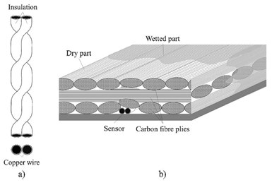
Linear dielectric sensor geometry (a) and diagram of how it is implemented in a composite laminate (b). Photo Credit: Fig. 1, “A novel dielectric sensor for process monitoring of carbon fibre composites manufacture” by K.I. Tifkitsis and A.A. Skordos.
Soon after, however, a project emerged where monitoring capability with carbon fiber reinforcement was required. “We came up with the idea that instead of using parallel wires, we would use twisted wires that are insulated — essentially copper wire that has some sort of a polymer coating on top. The twisting creates this kind of triangular region, which is where the resin gets into and gives us a signal. This triangular region also has significant length, so you have a bit better sensitivity, and the insulation protects the wires from shorting the signal with the carbon fiber.” The signal strength is actually proportional to the length of the wires and corresponding contact region, which also depends on the wire diameter and number of twists per unit length. The twisting also makes the pair more robust and eliminates the need for additional bonding to hold the wires in place on the RTM tool.
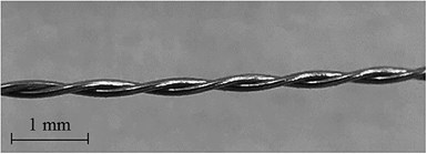
An 800-millimeter-long linear sensor made by twisting polyurethane enamel coated copper wires. Photo Credit: Fig. 4, “A novel dielectric sensor …”
Lab-scale demonstrations at Cranfield worked well, and Skordos’ team published the results in “A novel dielectric sensor for process monitoring of carbon fibre composites manufacture”, Composites Part A, vol. 123, 2019. As explained in this paper, an 800-millimeter-long linear sensor for flow monitoring was made by twisting two 136-AWP solid copper wires with polyurethane enamel coating (see image above). Each wire’s diameter was 127 micrometers and the twist pitch was 500 twists/meter. This sensor was placed in the center of a rectangular RTM tool (see image below).
The 800-mm-long linear dielectric sensor can be seen stretched along the centerline of the 900-mm-long RTM tool for Cranfield University’s initial CFRP RTM trials. Photo Credit: Fig. 5, “A novel dielectric sensor …”
The resin flow sensor was evaluated during RTM of two carbon fiber-reinforced polymer (CFRP) panels sized 900 x 340 x 3.3 millimeters thick. The panels used a preform made with nine plies of Hexcel (Stamford, Conn., U.S.) HexFlow RTM6 epoxy resin was injected at 120 °C and 2-3 bar with vacuum pressure at 10 millibar. The preform comprised 9 plies of HexForce 5-harness satin fabric with an areal density of 375 grams/square meter and resulting volume fraction of 57%. After the preform was infused, temperature was ramped at 1.5°C/minute to 160°C for a 2-hour-cure.
A cure monitoring sensor was made using 1.2 meters of twisted wire woven into a patch 20 x 20 x 0.5 millimeters in thickness using the miniature loom shown below. “We create a grid with the sensing wire so that we can fit a significant length in a small region,” says Skordos. “This longer-length of the linear sensors improves the signal strength, and thus makes this sensor more sensitive to the changes in cure.” Doesn’t the weaving hurt the sensor? “The sensor is quite robust,” says Skordos, “and those coatings are mostly developed for coil applications, so they can take quite a bit of curvature.”
Two isothermal experiments were carried out at 150 °C and 160 °C using neat RTM6 resin to the woven sensor. This cure sensor was also tested in an RTM trial using a 6-ply HexForce preform and RTM6 epoxy. Both sensors were connected to a Solartron 1260 Impedance Analyzer to acquire resistance and capacitance of the overall system, and in-house computer code developed using LabVIEW software was used for data acquisition.
Woven cure sensor (right) and loom used to produce it (left). Photo Credit: Fig. 7, “A Novel dielectric sensor …”
The results validated that both flow and cure monitoring were possible using these sensors. Skordos then saw a call for projects from the Technology Pull-Through (TPT) Program at the National Composites Centre (NCC, Bristol, U.K.) and decided it was a good opportunity to advance the technology further.
TPT demonstration
“TPT is in its sixth year now,” says Jack Alcock, TPT program manager at the NCC. “The program aims to help new technologies push through the ‘valley of death’. It targets novel and cutting-edge developments at universities and tries to advance these to an industrial scale. The goal is to show different sectors and companies where these technologies can be applied. We also tackle the challenges of going from TRL [technology readiness level] 1-3 up to TRL 6 and beyond, and we demonstrate technology beyond lab scale. We select technologies based on technical merits but also look for opportunities to aid and support industry to manufacture more efficiently and make their products smarter and more sustainable.”
The project submitted by Skordos’ team at Cranfield was accepted by TPT and work began. “There was quite a bit of effort to optimize the wire,” says Skordos. “We had used the first wire available that had the temperature range we wanted. Within the NCC development, different wires were assessed for their performance and response.” Part of this investigation notes that some coatings were less robust than others and had a potential to crack during weaving into cure sensors, for example. NCC selected wire for the sensor and then implemented it RTM trials, advancing the design infrastructure and connections, says Skordos. “The experiments we ran with the NCC were successful in monitoring resin flow and resin cure,” says Skordos. “That point is where our team stopped in terms of this sensor development.”
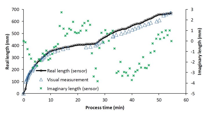
“We successfully put the sensor technology through its paces at 7 bar and 180°C, which are typical aerospace processing parameters,” adds Alcock. “We also developed some of the models used for selecting sensor materials and for manufacturing the sensor at a more industrial scale, including the twisting of the wire. For us, this project was really successful. The sensors survived the RTM trials and captured data accurately which we validated using visual observations. For example, we used transparent tooling to visually track the resin flow front as well as what the digital data acquisition was showing us. This helped us have confidence that even with non-visible processes, these sensors will show us what's actually going on.”
Starting the project with Meggitt
“As part of the TPT program,” notes Alcock, “we disseminate progress updates to the NCC members about these projects. Meggitt [Coventry, U.K.] has been a member of the NCC for a number of years, and this is one of their member benefits — to see these technology developments as they become available for potential solutions to their current challenges.” Alcock says Meggitt expressed an interest in working with the linear dielectric sensor developed and wanted to integrate it into some of their ongoing research. “We were then able to join ongoing activities between Meggitt and the Advanced Manufacturing Research Centre (AMRC, Catcliffe, U.K.) to put those sensors into an actual component.”
Experimental setup at Meggitt using linear dielectric sensors for flow and cure monitoring, attached on the tool used in an RTM press (top and in background of bottom) and connected to an analyzer — built from off-the-shelf modules from local supplier Advise Deta —which then sent data to a PC for analysis. Photo Credit: Meggitt
“I was in the NCC committee meetings, and saw that this technology could be a good fit with our research program,” says Petros Karapapas, principal engineer at Meggitt (Loughborough, U.K.). “I’ve been with Meggitt for four years. It's a big company, with three sites in the U.K. and multiple sites in the U.S. that make both metallic and composite parts. For example, carbon-carbon brake discs, F-35 exhaust flaps and fuel tanks for Sikorsky special mission helicopters. The division I work for makes airframe systems, not wings or empennages, but mainly secondary structures. We also do anti-icing for helicopter and engine air intakes, and we have a site just north of London that makes radomes.”
“Like most companies that manufacture composite parts, we are trying to move to more digital technology,” explains Karapapas. “But because a lot of the parts we make are small batch, complex parts, most are still made by hand. However, now that we're moving to bigger engines, like the Rolls Royce Ultra Fan, we need to look at how to make bigger components and also at a higher rate of production. So, we cannot afford to do all of the layup by hand nor all of the post-processing inspection and testing of each component.”
The linear dielectric sensor presented by the TPT program looked attractive, he says, because it could be fully bespoke. “It can be one meter long and bent, left or right, to fit into any kind of tool. And I wouldn’t have to modify the tool, which was important. The amount and quality of information that we'd be able to get was also important to us, having in mind the complex parts that we’ll be making in the future and for parts like radomes. These are actually expensive parts to make, because of the specialized materials used for radar transparency, so being able to control the RTM process is really important. We also had in mind other programs that have to do with new generation aircraft, where I can see this technology will be of paramount importance to us.”
Designing the demonstration
The trials at Meggitt would monitor flow and cure of Solvay (Alpharetta, Ga., U.S.) EP 2400 epoxy during RTM of a 1.3 meter-long, 0.8-meter-wide and 0.4-meter-deep composite housing for a commercial aeroengine heat exchanger. “The demonstration part was designed with reference to actual Ultra Fan specifications and was full-size,” says Karapapas.
“For this program, part of our work at NCC was to retrofit the linear sensors,” says Alcock, “because they weren't designed for the demonstration part and the tooling wasn't designed for these sensors. We wanted to have minimal to no impact on the program already in progress between Meggitt and the AMRC. We were able to work out a mechanism for integrating these sensors without requiring any tooling modifications or any drastic changes to the manufacturing process. During the few hours of resin injection and cure, we monitored the degree of cure in terms of the impedance the sensor measured in the resin. We also successfully monitored the resin flow front across the part. We recorded all of that data and developed data processing models and post-processes for presenting that data in terms of what went on in the aeroengine housing component’s manufacture.”
“For us, the gain was that we were able to use a technology that gives us eyes into the curing without modifying the tool,” says Karapapas. “It took less than one hour to custom fit the sensor into the tool. This flexibility and installation speed plus the amount and quality of information that we're able to get was important to us.”
Flow monitoring: Comparison of visual measurement with dielectric flow measurement at 1 MHz using linear flow sensor during glass top RTM trial under 4 bar clamping pressure. Photo Credit: Fig. 16, “Optimisation of an in-process lineal dielectric sensor for liquid moulding of carbon fibre” by T.S. Mesogitis, A.A. Skordos, et. al., Composites Part A: Applied Science and Manufacturing, Volume 140, January 2021.
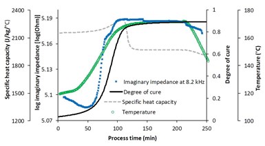
Cure monitoring: woven cure sensor response during cure stage of RTM process at 7 bar clamping pressure including imaginary impedance evolution at 8.2 kHz (blue x) and comparison with degree of cure development (black line) and the evolution of specific heat capacity (gray dashed line). Photo Credit: Fig. 17, “Optimisation of an in-process lineal dielectric sensor ...”
“We were also able to validate cure of the resin,” he continues. “Our vision is that, in the near future, that data can be used to reduce post-processing and NDI testing. Right now, we make test panels alongside such RTM parts and then we do DMA and mechanical tests on them to validate the cure cycle. But with this sensor, that won’t be necessary.”
“We were also able to gain a sense of validation through the manufacturing process parameters,” says Alcock. “We could see when the resin was injected — a quite sharp spike in resistivity — and then we could see when we closed off the injection and the cure was started. And we could correlate the data that we were seeing from the sensors with what the manufacturing process was doing. Within the Meggitt project, we ended up at TRL 4-5, and they can advance it to where they need depending on their specific programs and parts.”
Cost, interrogator/analyzer and data processing
Are these linear dielectric sensors expensive? “You get the twisted wire in kilometers, and it's a kind of off-the-shelf product, so it’s going to be cheaper than a fiber optic sensor, for example,” says Skordos. “These sensors are very cheap in comparison to others,” Alcock agrees, “and are quite simply manufactured as well by just twisting. So, the sensor cost is quite negligible. The ease of installation is another aspect. Your labor costs would probably be the highest input, but even then, as we’ve said, it is relatively easy and quick to install.”
“We are working with Airbus on another project implementing fiber optics,” adds Karapapas. “And it's not only the cost, but the time to embed the fiber optics into a composite tube which almost brought the project to a breaking point because all the interference that you get from the fiber and fabric itself, even if it's very fine-denier fabric, the imprint that it puts on the fiber optic actually affects the measurements. Don't get me wrong, the fiber optics will give you other things that this dielectric sensor may not give you — such as information about strain, loads, temperature etc. But as I said, the practical aspect of embedding fiber optics into composites are far more complicated and things like birefringence comes into play.”
Karapapas quotes some cost figures from in-house research at Meggitt: “Plain fiber optics cost £20/meter, but ones with Fiber Bragg Grating (FBG) sensors averaged £250/sensor (≈€300/sensor). Meanwhile, this linear dielectric sensor is nowhere near that. It is something that you can almost buy from a DIY store.” He also notes that the interrogator or analyzer for fiber optic sensors costs roughly £10,000 (€12,000). Skordos notes that cost for the interrogator used to collect signals from the linear dielectric sensors is a consideration. “When we do this kind of work in our lab, we use an impedance analyzer, which is a very accurate piece of equipment that costs at least £30,000 [≈€36,000]. But the NCC used a far simpler interrogator that comprises essentially off-the-shelf modules from a local supplier [Advise Deta, Bedford, U.K.]. So, they put those modules together as the application demands, so you can have far cheaper implementations.”
The analyzer system used by NCC, says Alcock, was just a computer with the relevant software on it, totaling $7-8,000 for everything to be put together. “This included the specialist software installed on the computer and 16 or so data ports for this particular setup. This is probably what would be used by industry, in terms of the level of accuracy that's required. From my understanding, the actual hardware and materials for this technology are relatively low. It’s probably the labor costs which are going to be time-consuming aspects, but as Peter said, we've got quite an efficient way of integrating them and we’ve demonstrated that you don't need any modifications to your tooling or process.” He admits that future designs and industrial-scale production may use automation, “but at least we’ve demonstrated what is possible.”
And what about the software in LabView that NCC developed? “We did develop a bit in the modeling aspects and in the post-processor to be able to take the data and make some sense of it,” says Alcock, “but Meggitt and other companies could work with us to get this post-processing set up in the way they need.”
Meggitt’s path forward
“This was our first step toward digitization and automation,” says Karapapas. “I want to know what's going on inside the part manufacturing process while it's happening, as opposed to opening the box and seeing what happened afterwards. I want to know in advance, so that I can monitor my process and workflow and feed that into our ERP system so that I can know what components to make, what people I need and what materials to order. I want to know whether the parts are okay and to take action to address this during processing.” This data can also feed back into better designs and processes. “In the future, we hope to involve NCC early on, so that we can design the production tool with dedicated locations for the sensors,” adds Karapapas. One advantage of these linear sensors, notes Alcock, is that they allow monitoring resin flow continuously along a length, which significantly reduces the number of sensors needed in a part or tool.
Related Content
From the CW Archives: Airbus A400M cargo door
The inaugural CW From the Archives revisits Sara Black’s 2007 story on out-of-autoclave infusion used to fabricate the massive composite upper cargo door for the Airbus A400M military airlifter.
Read MoreComposites manufacturing for general aviation aircraft
General aviation, certified and experimental, has increasingly embraced composites over the decades, a path further driven by leveraged innovation in materials and processes and the evolving AAM market.
Read MoreCarbon fiber satellite arm reduces weight, simplifies assembly onto naval vessels
Satcom developer EM Solutions partnered with ACS Australia to replace an aluminum arm design with a 65% lighter, one-piece, corrosion-resistant carbon fiber/epoxy alternative.
Read MoreNanopoxy, Nione jointly develop nanostructured epoxy resin
Epoxies featuring nanometric niobium pentoxide particles promote toughness, UV radiation resistance and other performance gains.
Read MoreRead Next
DC dielectric sensors for industrial composites production
Synthesites in situ process monitoring enables cure decisions based on real-time Tg evaluation that can reduce cure cycles by up to 50%.
Read MoreCombining AC and DC dielectric measurements for cure monitoring of composites
Lambient Technologies advances dielectric analysis (DEA) for more reliable, affordable composites manufacturing.
Read More

