New dimensions in sailing
A one-piece airfoil with a flexible 3-D carbon composite structure captures the performance sailing market.
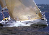
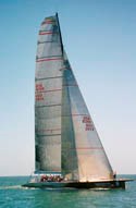
North Sails has captured more than half of the estimated $150 million (USD) market for sails on high-end racing and performance-cruising yachts and nearly 100 percent at the market's top end, having flown every sail on every boat in the last two America's Cup events and the most recent Volvo Around the World Race.
|
Founded in 1956 by yachtsman and Olympic medalist Lowell North, and now the largest division of North Marine Group (Milford, Conn.), North Sails makes all types of sail products and related accessories. Annual sales amount to about $80 million. For racing and other high-performance yachts, the company crafts downwind spinnaker sails from traditional nylon or polyester sewn panels — but tradition ends where upwind main sails and head sails begin. North Sails constructs these often massive (as large as 500m2 or nearly 600 yd2) sails in one piece. Made from carbon and aramid composites, these flexible structures are molded in a unique process at its Minden, Nev.-based 3DL division. |
The 3DL process was the early 1990s invention of Luc Dubois and J.P. Baudet, sailors and sailmakers who came up with the concept and equipment to make a lighter, stiffer — but still flexible — one-piece airfoil that Bill Pearson, 3DL's director of operations, says revolutionized his industry. "Sails have been pieces of woven fabric stitched together since the beginning of time," says Pearson. "With this development, we have broken through a 5,000-year-old technology wall."
Performance sailmaking is primarily concerned with the tensile stiffness, or modulus, of material, rather than its strength. "A sail tends to operate in the region of 10 percent of its breaking load," Pearson says. "It is way overbuilt in terms of strength, but it isn't engineered for strength. It is engineered to be stiffer, or more resistant to stretching."
Pearson points out that the use of advanced composite materials in a one-piece sail eliminates the dimensional inaccuracies that are inevitably "manufactured in" when traditional sails are assembled from multiple pieces by hand. "In a conventional panel sail, some panels carry more load than others and the stretch of the sail is usually higher than expected," Pearson says. "Even if a sail is smooth and fair, it will have uneven loading due to assembly errors." 3DL avoids these errors through computer-controlled place-ment of fibers.
A mold for all sails
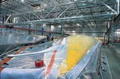
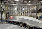
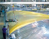
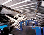
The heart of the invention is a super-sized, articulated male mold that can be adjusted in three dimensions to match the complex curvature and configuration of an entire custom sail in the three-dimensional horizontal and vertical profile it assumes when filled with wind. This is its working or "flying" shape. The mold consists of pneumatically actuated lifting mechanisms (lifters) and a segmented surface structure made up of parallel, round pultruded rods (called battens) and supporting rectangular cross bars. This surface structure is covered by closed-cell neoprene foam (Valley Rubber and Gasket, Sacramento, Calif.) that provides an insulating base layer for the layup. The foam toolbed is covered with a loosely fitted, metallized nylon sheet that reflects energy back through the part during infrared heating/curing to increase cure efficiency. The mold not only enables fabrication of the huge sails in one-piece, but facilitates layup and cure of the sail laminate in its flying shape as well.
The mold's lifters operate similarly to extension mechanisms that raise work platforms aloft for tree or utility line maintenance. As the lifters raise and lower, the round battens roll into new positions. In effect, the parallel batten design gives the surface structure flexibility comparable to that of a spinal column, which allows the body considerable leeway to bend and twist without breaking. Glasforms Inc. (San Jose, Calif.) pultrudes round glass/polyester bars for the battens, with diameters of 6.35 mm, 12.7 mm, 19 mm and 25.4 mm (0.25-inch, 0.5-inch, 0.75-inch and 1-inch). For the cross bars, the company pultrudes rectangular profiles measuring 6.35 mm by 63.5 mm (0.25 inch by 2.5 inches). The battens are bound together by welting that is made from Spectra ultrahigh molecular weight polyethylene (UHMWPE) fibers, supplied by Honeywell Advanced Fibers and Composites (Colonial Heights, Va.), and Dyneema high-strength, high-modulus polyethylene fibers, supplied by DSM Dyneema (Geleen, The Netherlands). The bars, battens and welting form an adjustable male mold surface with sufficient strength to safely permit sailmakers to walk on the toolbed.
3DL's current computer-controlled mold-adjusting system uses two pneumatic cylinders on each lifter, which drive an attached vertical worm gear one quarter turn at a time, adjusting its lifter 1 mm/0.0394 inch per turn. Dedicated software enables the lifters to continuously poll each other and make simultaneous corrections, so the entire adjustment takes place in only eight minutes.
Following adjustment, laser scanning equipment built by 3DL checks the mold to verify the design shape. Two laser plotters, riding on opposite ends of an overhead gantry, make one pass over the mold. The lasers focus in the center of the mold and generate data from 300,000 data points that delineate the location of the mold, the sail design shape and the location of the lifters. Software calculates errors from each of the data points and signals the lifters to adjust as necessary, within a ±2-mm (±0.08-inch) tolerance. These adjust- ments take about five minutes.
The entire process of adjusting and verifying the mold configuration takes from 20 to 30 minutes. In contrast, several hours were required to adjust the company's first-generation molds, which were individually driven by electric motors and horizontal worm gears. (In the original prototype, the lifters were driven by 150 electric motors removed from 150 Black & Decker electric hand drills, bought by the cost-conscious inventors at their local hardware store.)
Second only to the mold design in importance is material selection. In the past decade, 3DL has built sails from a number of high-tech fibers: aramids, Vectran polyvinyl alcohol fiber (PVA, Kuraray America, New York, N.Y.), Zylon p-phenylene-2,6 benzobisoxazole (PBO, Toyobo Co., Osaka, Japan), Spectra UHMW polypropylene and Pentex high-performance polyethylene naphthalate polyester fiber (both from Honeywell) and carbon fiber reinforcements. Experience has led to selection of high-modulus Twaron aramid from Teijin Twaron (Arnhem, The Netherlands) and a carbon fiber carefully selected from among many candidates for its adaptability to North Sails' flexible composite application. Both provide the optimum combination of properties for high-performance sails. Depending on the application, 3K, 6K or 12K tows are used, with the smaller tows preferred for higher-performance sails.
From flying shape to fabrication
Usually, when high-level racing teams order sails, they not only design the fiber architecture but specify fiber placement requirements as well. For other clients, North Sails maintains a library of more than 500 structural yarn layouts that can be married to the flying shape by in-house computer processors. In either case, two design files are sent to 3DL. One describes the sail's geometry, preferred materials and the flying shape. The other defines finishing details.
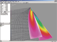
From these files, 3DL's File Processing department uses the company's own software to create 19 different files that will be used to drive nesting and cutting of films, mold adjustment, fiber placement, lamination and other steps of the manufacturing process. A three-dimensional computer model is created in 3DL's DesMan program, which treats rig, sail and hull as a working system rather than as individual components. The DesMan molded sail shape model is then folded into the Spiral program, where the goal is to achieve a flying shape that holds its form through a specific wind range with the least amount of material. Flow2000 software models air flow over the sails and produces a pressure map on the sail surfaces. This pressure field is then linked directly to North Sail's Membrain software, which takes the sail shapes from the DesMan model and the pressure map from Flow2000 and applies pressure to the sail/rig combination, deforming the mast and sail as a single structure. The design process creates a detailed analysis that models the flying shapes of the sails, all loading in the mast-sail unit, and the stress and strain in the yarn structure of the sails. (In essence, the stress on the sail's structure is the load on the yarn, while the strain is the amount of movement or stretching of the yarn.) A fifth piece of software, Virtual Wind Tunnel (VWT), is in development and promises further refinements in tailoring, Pearson says. Once confident in its design, 3DL proceeds to build the sail.
Binding film to fiber
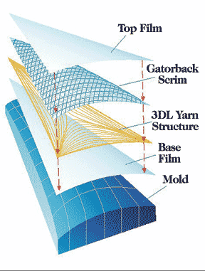
The first step is coating and cutting a base film, which becomes the starboard side of the sail and forms a barrier layer that prevents wind from passing through the sail in use. 3DL uses Mylar polyester film from DuPont Teijin Films (Tokyo, Japan), 0.5 mil to 0.75 mil in thickness (1 mil = 0.0254 mm/0.001 inch), which has the best blend of stiffness and suppleness for the application. "Films with higher modulus, like aramid or DuPont's Kapton polyimide film, have proven to be too brittle in practice to withstand much flex fatigue, and more supple films like Tedlar and Nylon (also from DuPont) are not stiff enough for high-performance sails," Pearson explains. For cruising applications, UV inhibitors may be added to the Mylar film and to the resin system.
One side of the clear film is coated with a thin layer of a 3DL-formulated thermoplastic hot-melt adhesive, applied to the film by means of an industrial rotogravure converting machine. Oven-dried adhesive pellets are vacuumed into the machine's screw-type extruder and melted at 215.5°C/420°F as they churn through the screw. The coating leaves a faint but visible pattern on the film, which aids in quality inspection: if the adhesive has properly flowed and bonded during lamination, the film is completely clear again.
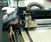
The coated film is transported to 3DL's laser cutting facility, where Eastman Machine (Buffalo, N.Y.) plotter equipment cuts the film in nested patterns and marks it for mold location, all according to CNC programming created from the original design files. (Eastman acquired this laser technology in 1995 from North Sails Group, which developed the system for sail-making.) The cut film pieces are butt-joined, with no overlapped seams, using pressure-sensitive adhesive tape of the same weight and material as the film. Another film, of the same material and configuration, but without adhesive, is prepared for use as the top of the vacuum bag during lamination.
A layer of 3DL's trademarked Gatorback scrim is similarly prepared. The scrim is an open-weave, 12-mm to 24-mm (0.472-inch to 0.945-inch) triangular pattern of off-axis aramid fibers on Mylar film. In sails, scrim provides tear strength and handles secondary loads. The primary corner-to-corner structural fiber pattern carries the major sail loads, but the secondary reinforcement provided by the off-axis aramid scrim catches minor transverse loads that the structural fiber orientation may miss. For greater durability, a lightly woven polyester taffeta, woven by Milliken (Spartanburg, S.C.) using 70 denier yarn from Nan Ya Plastics Corp. (Livingston, N.J.), may be added to the ply schedule or, some-times, polyester or aramid axial yarns are bonded directly to the scrim. If parallel aramid fibers are to be added to the off-axis pattern, they are bonded to the scrim in the converter machine at the same time the adhesive is applied.
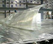
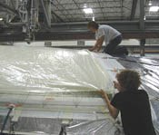
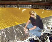
In the meantime, one of the molds has been adjusted and laser-scanned, according to the sail design file program. When the mold is ready, the Mylar base film is spread across the metallized nylon cover, adhesive side up, and manually tensioned into place by a simple pulley purchase system. First down in the mold, the Mylar provides a carrier for layup of the structure and serves as the bottom layer of the vacuum bag during lamination.
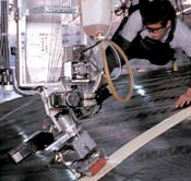
After the base film is in place, 3DL's fiber placement system lays resin-coated carbon or aramid yarn in a complex curvature pattern that follows the specified primary structural loads. The yarn passes through a 20-mm/0.787-inch wide resin chamber and segmented roll-coating device on the head. The fiber-placement head is attached to the bottom end of a vertical device called a Z-car, which is suspended from an overhead gantry that runs the length of the building. Attached to the Z-car is a climate-controlled Plexiglas enclosure containing 13 spools, each wrapped with 1.4 kg to 4.5 kg (3 lb to 10 lb) of yarn.
The resin used for yarn layup is a custom thermoplastic/polyester system, with solvent and catalyst. Developed in-house, the resin "does crosslink to some extent but remains thermoplastic even after crosslinking," explains 3DL's chemical engineer, Michael Runow. This multiphase resin combines two distinct polymers with different properties. One provides long-term bonding between the fiber and matrix. The other bonds the resulting composite to the film. "This unique system is an important part of our technology," Pearson says.
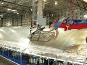
During yarn placement — an oper-ation that can take from 2 to 40 hours, depending on the size of the sail — workers begin building the vacuum bag, first laying breather felt around the perimeter of the mold and then attaching vacuum ports through the felt. Technicians oversee and assist in the manufacturing process from a hori-zontal position above the mold, lying in harnesses adapted from the sport of hang gliding, which are suspended from overhead gantries that span the length of the building. Each gantry can serve two molds.
When the layup is complete, the designated scrim is pulled out over the mold, adhesive side down, and tensioned into place over the yarn structure. Then, the top vacuum bag layer of Mylar film is pulled over the mid-film scrim and secured to the mold over breather felt. One atmosphere of pressure (14.7 psi/101.35 kPa) vacuum is pulled, which takes about 20 to 30 minutes.
The part is now ready for lamination by conductive or infrared heating/ curing. Infrared heating is used for all aramid sails. The infrared heating unit, approximately 0.6m by 1.2m (2 ft by 4 ft), is suspended overhead and travels over the surface about 203 mm/8 inches off the laminate, radiating heat directly into the laminate. A steady application of 149°C/300°F heat is needed to ensure proper resin and adhesive flow inside the laminate. While infrared heating is four to five times faster, a similarly suspended conductive heater of about the same size is used for carbon fiber sails because it offers 3DL better heat control. The conductive heater consists of a basket-shaped Teflon PTFE-impregnated fiberglass blanket with an integrally woven carbon fiber mat that acts as the heat source. An interior silicon air bladder allows the blanket to conform somewhat to the surface of the mold/part.
A visual quality check is done by a flying technician during layup and lamination and before the cured part leaves the mold (visual inspection is considered sufficient to verify adhesive flow and bonding). After 10 to 20 minutes, the cured sail is stripped from the mold, the vacuum bag is removed and the sail goes to the quality control floor for a more extensive inspection. Sails are stored for five days on site to permit the resin and adhesive to reach 85 percent cure. The sails are then folded and shipped to a traditional sail loft for trimming, edge and corner finishing and installation of rings, turning blocks and other attachment hardware.
|
Today, 3DL runs 11 molds 24/7, 362 days a year, fabricating about 100 sails per week, ranging in size from about 30m2 to 500m2 (36 yd2 to 598 yd2). A twelfth mold, now under construction, will use 280 lifters to adjust the tool to specific sail configurations in sizes as large as 18.5m/20.2-yd at the foot (the sail's bottom edge) and a 37m/40.5-yd luff (the edge of a sail nearest the bow). |
Around the world ... and then some
After her first Around the World race, Ellen MacArthur (also see HPC July/August 2000, p. 7) said her 3DL sails could "go around again." While she didn't use them again, of course — it would involve too great a risk — her comment supports Pearson's contention that a 3DL sail "retains an optimum aerodynamic flying shape longer than cut-and-sew panel sails, or the segmented string sails [3DL clones] now appearing on the market." At the America's Cup level, a sail is considered durable if it lasts between 25 and 50 hours of racing. Pearson points out that a woven Dacron cruising sail of sewn panel construction would be expected to have an ultimate life of 8 to 10 years; however, that sail would be an aerodynamic liability in performance sailing well before the end of its first year, he says.
"The use of continuous fiber and a three-dimensionally molded shape creates a sail that is both lighter and more stretch-resistant than anything that has come before," Pearson maintains. "This allows the sail to better retain its aerodynamic shape over a wide wind range, and for a longer period of time, than was ever before possible."
Related Content
Novel composite technology replaces welded joints in tubular structures
The Tree Composites TC-joint replaces traditional welding in jacket foundations for offshore wind turbine generator applications, advancing the world’s quest for fast, sustainable energy deployment.
Read MoreMFFD thermoplastic floor beams — OOA consolidation for next-gen TPC aerostructures
GKN Fokker and Mikrosam develop AFP for the Multifunctional Fuselage Demonstrator’s floor beams and OOA consolidation of 6-meter spars for TPC rudders, elevators and tails.
Read MoreVIDEO: One-Piece, OOA Infusion for Aerospace Composites
Tier-1 aerostructures manufacturer Spirit AeroSystems developed an out-of-autoclave (OOA), one-shot resin infusion process to reduce weight, labor and fasteners for a multi-spar aircraft torque box.
Read MoreGKN Aerospace, Joby Aviation sign aerostructures agreement
GKN Aerospace will manufacture thermoplastic composite flight control surfaces for Joby’s all-electric, four-passenger, composites-intensive ride-sharing aircraft.
Read MoreRead Next
Developing bonded composite repair for ships, offshore units
Bureau Veritas and industry partners issue guidelines and pave the way for certification via StrengthBond Offshore project.
Read MoreVIDEO: High-volume processing for fiberglass components
Cannon Ergos, a company specializing in high-ton presses and equipment for composites fabrication and plastics processing, displayed automotive and industrial components at CAMX 2024.
Read MorePlant tour: Daher Shap’in TechCenter and composites production plant, Saint-Aignan-de-Grandlieu, France
Co-located R&D and production advance OOA thermosets, thermoplastics, welding, recycling and digital technologies for faster processing and certification of lighter, more sustainable composites.
Read More


