Next-generation braiding for next-gen bike
When Grenchen, Switzerland-based Bicycle Manufacturing Co. (BMC) decided to braid the tubes for its impec racing bike frame, the use of carbon fiber and the complex tube designs and shapes prompted the use of radial braiding technology from August Herzog Maschinenfabrik GmbH & Co. KG (Oldenburg, Germany)

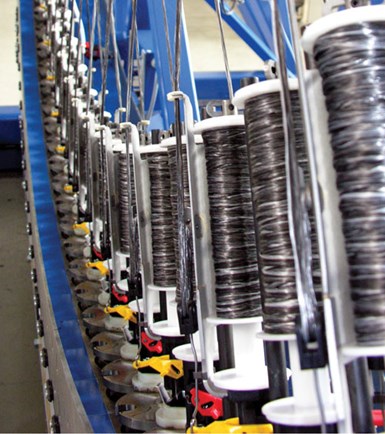
Unlike conventional braiding equipment, which forms the braid in parallel to the bobbins and requires fiber movement that damages stiff, low elongation carbon fibers, Herzog’s radial braiding system for carbon fiber preforms reduces the span of fiber movement to only 0.10 inch/2.54 mm, and the fiber goes straight over the tensioning unit only once, not repeatedly, forming the braid at a 90° angle to the bobbins. This results in much less fiber breakage. Source: BMC
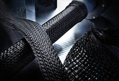
Braiding interlaces three or more yarns together, forming a seamless textile preform over a mandrel. The textile’s interlocked fibers excel in torsional strength and impact resistance. Braided reinforcements also feature channels between the yarn bundles, which aid resin distribution during vacuum infusion and resin transfer molding. These attributes recommend braiding for bike frames.
Braiding machinery can be programmed to tailor fiber angles and densities to meet specific load conditions by increasing or decreasing the fiber angle. And additional layers may be added by “overbraiding” — that is, reversing the mandrel and braiding over the previous layer — either along the mandrel’s entire length or only in specific locations. Further, different fiber sizes and types may be combined to achieve a wide variety of braided fabrics.
When Grenchen, Switzerland-based Bicycle Manufacturing Co. (BMC) decided to braid the frame tubes for its impec racing bike frame, however, the use of carbon fiber and the complex designs and shapes of the tubes challenged the limits of conventional braiding technology. Guido Grave, managing director at BMC’s braiding equipment supplier, August Herzog Maschinenfabrik GmbH & Co. KG (Oldenburg, Germany), explains that on traditional braiding equipment, yarns are pulled from numerous bobbins that are loaded on carriers driven by “horn gears.” Different arrangements of horn gears and bobbins produce different textile constructions. Each carrier follows a sinusoidal path that causes the distance between the carrier and the braid point to change periodically. When the carrier moves toward the braid point, this would causes slack in the yarn and loss of control if the machine maker did not compensate for the slack by equipping every carrier with a spring-loaded recoiling unit that, due to the limited space, works with small turning points of 180° and 360°. Carbon fiber, because it is brittle and exhibits very low elongation, resists this movement as it passes through the tight angles, resulting in a lot of fiber damage.
The preforms for BMC’s impec frame tubes, however, are made on a radial braiding machine developed by Herzog. “We developed radial braiding to reduce fiber damage when making preforms from carbon fiber,” notes Grave. “In radial braiding, we actually shift the carriers so that the span is reduced by 80 percent.” The carbon fiber goes straight over the tensioning unit — only once, not repeatedly for each braiding overlay — resulting in much less fiber breakage. The braid is formed at a 90° angle to the bobbins, instead of parallel, which makes radial braiding visually distinct from traditional braiding.
In the quest for preforms with ever-increasing complexity, Herzog developed a laboratory-scale 3-D braider. “The equipment is amazing, using up to 500 bobbins, and can achieve almost any shape and design,” Grave claims. The possible shapes include L-shaped stringers and seamless rectangular beams. Grave adds that it can “interlock several layers in situ,” yet he admits, “it is very complicated, and thus, does so only on a small scale and at a very high price.”
Graves describes the equipment as an object of envy for universities but not practical for large-scale manufacturing, and yet he notes, “We learned very much about the 3-D braiding process through this development and have been able to incorporate some of the features into our traditional and radial braiding systems.” Hence, Herzog describes its radial braiding as 2½-D.
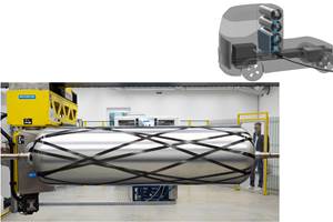
“It possesses the speed and low investment cost of a 2-D system,” says Grave, “but you can achieve a real 3-D preform.” However, a shaped mandrel is required. For example, the Airbus A350 XWB fuselage ring frames use a curved mandrel (see “Learn More”). For BMC, each bike frame tube has a different and precisely shaped mandrel.
Grave says Herzog’s 2½-D radial braiding also enables modifications in the weave pattern. Traditional 1 over 1 and 2 over 2 constructions, for example, result in frequent fiber undulation, which reduces the reinforcement’s strength compared to a layup of unidirectional tapes. Herzog’s system is able to produce a 4 over 4 construction with less undulation, resulting in a flatter fabric with greater strength.
“For BMC’s development of very tailored manufacturing in a high-wage country, radial braiding was the only possible solution to produce the tubes for the impec frame,” says Grave, noting that compared to competitive processes like tape winding and hand layup, braiding enables precise placement of much more material per unit of time. “It also offers greater process stability,” Grave contends. “This basically means less error. For example, the braiding machine is stable compared to many different workers performing hand layup. The machine will only do what it is programmed to do, so there is almost no product variability.”
These attributes are boosting the use of radial braiding not only in the impec frame and in aircraft structures, such as frames and stringers, but also in carbon fiber-reinforced automotive composites. “You will see our radial braiding process used in the automotive industry beginning next year,” Graves predicts, “because it also meets their speed and high productivity requirements while enabling the complex shapes and load-specific tailoring they are pursuing.”
Related Content
McLaren celebrates 10 years of the McLaren P1 hybrid hypercar
Lightweight carbon fiber construction, Formula 1-inspired aerodynamics and high-performance hybrid powertrain technologies hallmark this hybrid vehicle, serve as a springboard for new race cars.
Read MorePEEK vs. PEKK vs. PAEK and continuous compression molding
Suppliers of thermoplastics and carbon fiber chime in regarding PEEK vs. PEKK, and now PAEK, as well as in-situ consolidation — the supply chain for thermoplastic tape composites continues to evolve.
Read MorePlant tour: Teijin Carbon America Inc., Greenwood, S.C., U.S.
In 2018, Teijin broke ground on a facility that is reportedly the largest capacity carbon fiber line currently in existence. The line has been fully functional for nearly two years and has plenty of room for expansion.
Read MoreCryo-compressed hydrogen, the best solution for storage and refueling stations?
Cryomotive’s CRYOGAS solution claims the highest storage density, lowest refueling cost and widest operating range without H2 losses while using one-fifth the carbon fiber required in compressed gas tanks.
Read MoreRead Next
An impec-able bike frame: Handmade by machine
Long on technology firsts, this optimized, automated manufacturing process produces nothing short of the “perfect” bike frame.
Read MoreAll-recycled, needle-punched nonwoven CFRP slashes carbon footprint of Formula 2 seat
Dallara and Tenowo collaborate to produce a race-ready Formula 2 seat using recycled carbon fiber, reducing CO2 emissions by 97.5% compared to virgin materials.
Read MoreDeveloping bonded composite repair for ships, offshore units
Bureau Veritas and industry partners issue guidelines and pave the way for certification via StrengthBond Offshore project.
Read More


