Roll-wrapped golf club shafts feature sophisticated prepreg layup
Roll-wrapped golf shafts are produced through advanced laminate software program.
Most of the 100 million golfers worldwide would agree that their clubs are a vital part of the game. But what they might not realize is how a composite club shaft can be infinitely tailored to match a player's physique and ability and create that indefinable "feel" when hitting a shot.
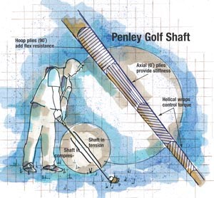
A swing at the little white ball involves a complex and dynamic interplay of many factors, which include the weight of the club head and shaft, shaft stiffness, the degree of shaft flex and twist (torque) and the relationship between the tip and butt shaft diameters -- all of which have to complement a golfer's strength and skill level to produce a comfortable experience. Notable among the forces acting on the club shaft are in-plane bending, caused by club head "droop" during the backswing, which puts the rear half of the shaft (facing the golfer) in compression and the front half (facing the ball) in tension. Extreme flex occurs when the club head lags behind the shaft during the downswing and follow through, causing bending. Torque is produced when the player swings the club over his or her shoulder, then down to the ball in a spiraling arc while bending his or her wrists.
For example, a shaft's "kick point" is the point on the shaft where the highest flexion occurs, as measured by holding the shaft at both ends and bending it. Stronger-swinging pro players prefer a high kick point, i.e., a stiffer tip, which gives the ball distance. A weekend player with a softer swing typically wants a lower kick point, or more flexible tip, which helps loft the ball into the air.
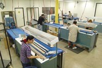
Composites have earned their huge share of the golf shaft market because a composite shaft's construction can be precisely designed to tailor characteristics like kick point. Penley Sports LLC (San Diego, Calif., U.S.A.) has the production capacity to roll-wrap more than 6,000 premium composite golf shafts per day, with the aid of its in-house composite laminate design software program that dictates exact fabrication details. The company's wide range of products is targeted to all levels of golfers, from amateur to professional, who desire enhanced performance.
"We make 300 different shafts and have over 3,000 different designs," says Carter Penley, founder of Penley Power Shafts, the precursor company to Penley Sports. "We can optimize any player's swing with composites' design flexibility."
Thin-walled tube design
A typical Penley golf shaft is a thin-walled tube ranging from 114 cm/45 inches to 127 cm/50 inches in length with an average weight of only 50g to 80g (1.77 oz to 2.83 oz). Carter Penley explains that the trick is to balance the competing requirements of shaft diameter, sufficient wall thickness to resist torque and flex, and overall weight.
The shaft's bending stiffness is determined by the moment of inertia (I) -- a geometric property of the shaft's cross-section that indicates its resistance to bending -- multiplied by the modulus (E) of the material used. To make a tube stiff enough for a golf shaft, you can increase E, or increase the moment of inertia, or both. Mathematically, the most efficient way to increase the moment is to increase the shaft radius, keeping wall thickness the same. But a larger-diameter tube with thin walls, though still stiff, is prone to failure by buckling. Penley's goal is to create a lightweight tube that not only possesses sufficient stiffness, but also maintains its shape and resists collapse, even under the very high imposed loads.
To achieve this level of performance, the company roll-wraps its clubs exclusively with aerospace-grade, unidirectional 12K carbon/ epoxy prepreg tape, typically made with high-modulus, PAN-based carbon fiber, in 30.5-cm/12-inch or 61-cm/24-inch widths. Prepreg suppliers include Toray Composites America Inc. (Tacoma, Wash., U.S.A.), Newport Adhesives and Composites Inc. (Irvine, Calif., U.S.A.), and Bryte Technologies Inc. (Morgan Hill, Calif., U.S.A.).
"We don't use woven broadgoods because they're too thick and don't deliver the strength we need for small-diameter shafts," says Penley.
When compared to steel, carbon's weight advantage allows a doubled or even tripled wall thickness to get adequate torque and flex resistance, at about one-half the weight of a comparably sized steel shaft, explains Penley. In addition, carbon fiber's vibration-damping characteristics mean that vibrations from ball impact are significantly reduced, compared to steel, minimizing player fatigue.
The design process starts with certain parameters that are fixed and normally don't change from shaft to shaft. The shaft tip, or "hosel," is typically set at an industry-standard 8.5-mm/0.335-inch diameter, for insertion into the majority of club heads. The diameter of the shaft's butt end is determined by standard grip sizes. Penley calls the ratio between the two the tip-to-butt aspect ratio, or TBAR, and says that 1.7 is an ideal TBAR value after watching and interviewing golfers about club feel.
"Eighty percent of golfers can hit very well at that number," says Penley. "We use that as our design driver, then let our target weight and stiffness dictate the modulus and fiber geometry."
The company has developed an in-house design analysis program called SRS, to handle the calculations involved in finding the optimum combination of design factors, including moment, fiber modulus and fiber architecture for each different type of club. Similar to a finite element analysis (FEA) program, SRS makes approximately 900,000 calculations along the length of a typical shaft, calculations which result in the type (modulus) of fiber required, the optimum fiber architecture, the number of wraps and the amount of fiber overlap. An important offshoot of the program is the determination of mandrel size and diameter. Lynco Grinding Co. Inc. (Bell Gardens, Calif., U.S.A.) supplies nearly all of Penley's steel mandrels, which number into the thousands to accommodate the wide range of club types and sets available, from drivers to short irons.
Software facilitates fabrication
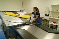
The SRS program is linked to AUTOCAD LT software from Autodesk (San Rafael, Calif., U.S.A.), an off-the-shelf program, which translates the design data into flat patterns. The patterns, in turn, are cut by a computer-controlled, automated sheeter/cutter manufactured especially for this application by Century Design Inc. (San Diego, Calif., U.S.A.). The machine unrolls the prepreg and cuts it at the appropriate length and fiber angles to make the pattern pieces, often called "flags." Anywhere from five to eight flags make up a typical shaft layup kit.
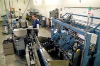
During production, a technician mounts a mold-release-treated mandrel on a roll-wrapping machine and inputs the corresponding SRS-developed wrapping program into the roll wrapper's controller. Each program comprises numerous "wraps" layers around the mandrel, which the controller translates into mandrel rotations, which are specified in degrees -- 720° means two complete wraps or plies, 1080° is three plies, etc. The computer-controlled layup also controls ply deviation to no more than 5° from the programmed load paths, to minimize off-axis fibers and loss of modulus.
Successful roll wrapping depends on exact placement of each subsequent flag on the mandrel to maintain laminate symmetry and prevent excessive material overlaps, which can lead to a condition called shaft spine, a lengthwise zone of higher stiffness. Penley's SRS program was originally developed with the intention of reducing or eliminating spine (SRS stands for spine reduction software) through precise fiber architecture and flag placement. While avoiding overlaps is important, it is critical to avoid gaps where plies must be butted together during layup. All shaft designs are digitally inspected by Penley for potential gaps prior to fabrication. "Gaps will really hurt you when it comes to shaft durability," notes Penley.
According to Penley, a typical shaft layup consists of two initial helical wraps, at an angle of +/- 45°, to control torque, followed by several 0° axial (lengthwise) wraps to control stiffness. The axial wraps are followed by hoop plies at selected locations to control flex and strength. The area just above the hosel is particularly prone to failure, because of its small diameter and proximity to the club head where flex forces are high. That area may receive not only extra hoop wraps but "floating" inserts of high-strength prepreg, typically carbon-boron/epoxy hybrid prepreg supplied by Specialty Materials Inc. (Lowell, Mass., U.S.A.), particularly for high-end pro shafts with a higher kick point.
Once the layup is complete, the shaft is overwrapped with clear polypropylene shrink film, using a Century Design wrapping machine, which helps to consolidate the layup during oven cure. Typical cure takes two to three hours, starting at ambient and ramping up to 135°C/275°F, then back down. Shafts are normally cured in batches of 100 and each of the facility's three ovens has a 500-shaft capacity. After cure, mandrels are hydraulically extracted with a Century Design device that restrains the shafts while removing the mandrel inside. Shafts are sanded, sized and painted, then packaged for shipment to golf club OEMs for assembly with heads and grips. Quality control includes dynamic analysis of selected shafts in a harmonic oscillation analysis testing device that rotates and flexes shafts to verify the flex, torque and TBAR characteristics and identify spine.
Parlaying experience
in new markets
Vijay Singh, Phil Mikelson and John Daly are some of the more notable names among the professional players that have adopted Penley shafts. Daly attributes his renowned hitting distance in part to Penley's ETA (Energy Transfer Accelerance) shaft, designed with very high stiffness and high kick point. The company's new, GAS (Geometric Angular System) shaft will generate some excitement in the golf industry, Penley predicts. Its patented sinusoidal (wave shaped) design, featuring hybrid prepregs, smoothes the loads and gains flex and torque characteristics not possible with a traditional tapered shaft.
The company is looking to parlay its experience in designing and producing golf shafts to other composite applications and markets. Its Applied Technology Group is aggressively branching out into new research and development areas, including aerospace and homeland security as well as other sporting goods.
"These shafts are sophisticated parts that require design and fabrication know-how," concludes Penley. "We can use our expertise to achieve high performance in other areas needing complex laminate design."
Related Content
Optimizing a thermoplastic composite helicopter door hinge
9T Labs used Additive Fusion Technology to iterate CFRTP designs, fully exploit continuous fiber printing and outperform stainless steel and black metal designs in failure load and weight.
Read MoreJeep all-composite roof receivers achieve steel performance at low mass
Ultrashort carbon fiber/PPA replaces steel on rooftop brackets to hold Jeep soft tops, hardtops.
Read MoreOptimized approach to predict delamination failure in CFRTP structures
ARRK Engineering and Mitsui Chemicals improved delamination prediction accuracy to help optimize absorbed energy/failure load for an overmolded TAFNEX CF/PP UD tape bumper beam.
Read MoreImproving carbon fiber SMC simulation for aerospace parts
Simutence and Engenuity demonstrate a virtual process chain enabling evaluation of process-induced fiber orientations for improved structural simulation and failure load prediction of a composite wing rib.
Read MoreRead Next
Developing bonded composite repair for ships, offshore units
Bureau Veritas and industry partners issue guidelines and pave the way for certification via StrengthBond Offshore project.
Read MoreVIDEO: High-volume processing for fiberglass components
Cannon Ergos, a company specializing in high-ton presses and equipment for composites fabrication and plastics processing, displayed automotive and industrial components at CAMX 2024.
Read MoreAll-recycled, needle-punched nonwoven CFRP slashes carbon footprint of Formula 2 seat
Dallara and Tenowo collaborate to produce a race-ready Formula 2 seat using recycled carbon fiber, reducing CO2 emissions by 97.5% compared to virgin materials.
Read More


