Rudder Gets New Twist With Composites
The U.S. Navy's specially contoured ship rudder commands composite construction.
Ship rudder design, historically, has been dictated by the need to minimize hydrodynamic drag, resulting in simple, linear designs analogous to vertically inclined wings. It is, therefore, far from obvious why the U.S. Navy's latest development is a rudder that is twisted in such a way that it presents a different angle of attack at different water depths. The reason for this departure from conventional rudder design has to do with the flow of water from the propeller. The primary purpose of a ship's propeller is to drive the hull forward by creating a rapidly moving mass of water in the direction opposite that toward which you wish to move (in accord with Newton's Third Law). However, to perform its task, a propeller must rotate, and this rotation introduces an undesirable secondary effect. As it propels water to the rear (along the 0° axis), it also creates a paddlewheel effect, propelling water to one side at the top of the propeller's arc of travel, and propelling water in the opposite direction at the bottom of its rotation. The combination of forces in the 0° and 90° directions causes water to flow at angles off the rudder's 0° axis. While the direction of the flow that strikes the rudder adjacent to the propeller's hub aligns with the rudder direction, the flow nearer the top and bottom of the propeller's swept area is misaligned with the rudder in one direction at the top of the rudder and misaligned in the opposite direction at the bottom. As a result, the angle of water flow varies along the rudder's span (the distance from top to bottom) and its chord (fore to aft length).
When water flows at high speed and at a slight angle over the rudder surface, the result is an undesirable phenomenon called cavitation. Cavitation occurs when water pressure falls to or below vapor pressure and vapor bubbles are formed. Repetitive collapse of these bubbles produces localized stress and vibration. This is bad news for naval ships. First, cavitation will damage the surface of the rudder and any protective coatings that have been applied, such as antifouling treatments. On a metal-skinned rudder, coating damage will expose the metal to the corrosive effects of seawater, thus increasing the need for inspection and maintenance. Second, cavitation will create (generate) noise. For a navy destroyer fitted with sonar devices designed to detect very quiet submarines at great distances, noise coming from its own rudder, located less than 500 ft/150m behind the sonar device, handicaps its ability to detect threats.
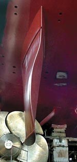
To alleviate cavitation, Dr. Young T. Shen of the Naval Surface Warfare Center Carderock Div. (NSWCCD, Bethesda, Md.) developed a "twisted rudder" design that incorporates a varying angle of attack from top to bottom (see photo, this page) — one that conforms more closely to the actual water flow pattern. During a development and testing program that was completed in June 2001, trials onboard the USS Bulkeley, an DDG 51 Arleigh Burke-class destroyer, using a prototype metal rudder constructed in accord with the new design showed that the proposed solution works well, delaying the onset of cavitation from 23 knots — within the normal operating speed range of Arleigh Burke-class ships — to 29 knots. Tests also demonstrated that the design had no negative impact on speed or steering capability.
COMPOSITE-FOR-METAL MANDATE
Since the original trial, however, the Navy has pursued a composite design for several reasons, not least of which is cost. The complex shape of the rudder's outer surface, for one, calls out for a composite construction, at least for the double curvature skins. "Twisted Rudder rudders are difficult and expensive to build out of steel," says Scott Lewit, president of veteran marine composites manufacturer Structural Composites (Melbourne, Fla.), noting that, unlike many composite-for-metal transformations, a composite solution, in this case, won't increase upfront cost. "The composite rudders are produced from molds that allow us to produce a rudder for about half the steel rudder cost."
The task of developing the manufacturing method for a composite twisted rudder has been given to Structural Composites. The company was originally awarded a $904,000 (USD) contract from the Office of Naval Research to build and test composite twisted rudders for DDG-51-class destroyers. This funded development of a demonstration technology, which will be used to test the design's survivability and resistance to environmental degradation. Contract funds above the original amount will come from the Office of Secretary of Defense's Defense Acquisition Challenge Program. The contract's full value will be $3.5 million, enough to fund a shipset of rudders for a two-year at-sea evaluation period.
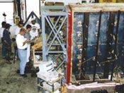
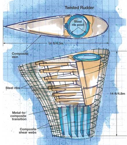
For the demonstrator program, Structural Composites will fabricate a full-size rudder, approximately 14 ft/4.3m across both the span and widest portion of the chord. Fitting the rudder to an existing ship with minimal changes is a requirement, necessitating that trial rudders have the same hub fitting that is used in all-steel designs to facilitate attachment to the rudder rib post on the trial vessel. To avoid an abrupt transition from steel to composite, trial rudders will feature a hybrid steel/composite design developed by Structural Composites and NSWCCD. The design includes a steel inner structure in the top portion of the rudder, provided by Maritime Applied Physics Corp. (Baltimore, Md.), which will transition to a foam-cored composite sandwich structure that features internal shear webs and an external surface of glass/vinyl ester composites, fabricated by Structural Composites (see drawing, p. 60). This steel/composite hybrid is being built with technical assistance from the Navy's NAVSEA 05M3 and NSWCCD personnel.
DESIGN AND MANUFACTURING
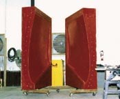
For this project, Structural Composites will use its Recirculation Molding process. A variation on light RTM, Recirculation Molding injects resin at relatively low pressure beginning at the lowest point of the mold, counterbalanced by a peristaltic pump that draws only 15 inches of vacuum (about half that drawn in conventional VARTM) through strategically placed vents, says Structural Composites' director of naval projects, Eric Greene. He notes that parts are typically infused vertically to take full advantage of gravity in air evacuation. During infusion, resin is drawn from the mold by vacuum and then re-injected to further facilitate removal of any trapped air. The low pressure permits use of a relatively inexpensive clamshell-type composite closed mold. The method permits comolding of the steel "skeleton" and composite sandwich in a single molding cycle.
Recirculation Molding was demonstrated by Structural Composites in a "stepping stone" Navy project called the Mine Countermeasure (MCM) program, in which a smaller untwisted rudder design, with a 7-ft/2.1m span and a chord 6-ft/1.8m wide at top and 5-ft/1.5m wide at bottom, was infused to demonstrate the process and create rudders for the Navy's "minehunter" vessels, on which nonmetallic surfaces help prevent detonation of magnetically triggered mines.
Core material forms made of 7 lb/ft3 (110 kg/m3) polyurethane foam (BASF, Central, S.C.) were used to fill in the general structure around the steel skeleton. On the full-size rudder, sections of formed polyurethane core are bisected by shear webs (vertical blue ribs in the drawing, p. 60) made from biaxial (±45°) glass fabric. The composites skins and steel structure are bonded with Plexus MA-310 supplied by ITW Plexus (Danvers, Mass.) though distributor Prairie Technology (Orlando, Fla.). The core, shear webs and steel skeleton are wrapped with (nominally) 25 plies (alternated at near 0° and 90° angles) of E-LM 1810 Uni, a reinforcement fabric consisting of unidirectional E-glass fibers (18 oz/yd2) stitched to 1.0 oz/ft2 binder-free chopped strand mat, from Vectorply Corp, (Phenix City, Ala), with strategically placed EnkaFusion 8004 infusion media, supplied by Colbond (Enka, N.C.). Because the rudder is infused vertically, reinforcements are tacked in place using Infuzene Vacuum Infusion Enabler (Westech Aerosol Corp., Port Orchard, Wash.), a spray-on material designed to solubilize during infusion and disperse in the resin to prevent binder-related interference with fiber/resin adhesion.
The full-scale rudder assembly is then encased in the mold and infused with 8100-50 vinyl ester resin from Interplastic Corp. — Thermoset Resins Div. (St. Paul, Minn.) catalyzed with Luperox DHD-9 from Arkema (Philadelphia, Pa.).
STEERING TOWARD SUCCESS
The infusion process for the Twisted Rudder will build upon lessons learned from the Navy ManTech-sponsored MCM project. A trial run on a full-scale rudder (sans steel component) is slated for this month, to prove the composite manufacturing method. Assuming all goes well, the process will be repeated in September with the steel hub structure in place. Finished rudders must be ready for installation in the March-May 2007 timeframe, when the test vessel is in port.
Greene anticipates multiple benefits for the Navy. On the MCM Rudder program, the use of composites enabled a 50 percent reduction in rudder weight from 5,772/lb to 2,820/lb. Use of a lighter rudder also affects the trim of the vessel, permitting removal of counter-weighting ballast from the bow. In the full-size Twisted Rudder to come, acquisition cost and survivability are the primary program drivers. The yacht-quality rudder surface will offer less form drag, which will translate to reduced fuel consumption. More importantly, the rudder's cavitation-reducing twist will minimize erosion damage and significantly reduce maintenance costs. "The noncorrosive structure will not deteriorate when subject to the aggressive environment downstream of the propellers," says Greene.
Greene believes that the composite rudders also may offer a much more survivable solution for surface combatant appendages. One of the most difficult challenges in designing a rudder for a naval ship is the ability to withstand underwater explosions, says Greene, noting that "the MCM design has been being optimized and tested for underwater blast resistance."
Although the demonstrator program only covers development of the hybrid steel/composite rudder, Greene says integration of a carbon fiber rudder post into the structure will produce a significantly lighter and stronger rudder/shaft assembly. He believes that an all-composite rudder could be viable for the DDG 1000-class destroyer, with the potential to reduce the magnetic and electrical "signatures" of the Navy's future surface combatant ship, which is currently in the design and demonstration stage.
Related Content
Novel composite technology replaces welded joints in tubular structures
The Tree Composites TC-joint replaces traditional welding in jacket foundations for offshore wind turbine generator applications, advancing the world’s quest for fast, sustainable energy deployment.
Read MoreGKN Aerospace, Joby Aviation sign aerostructures agreement
GKN Aerospace will manufacture thermoplastic composite flight control surfaces for Joby’s all-electric, four-passenger, composites-intensive ride-sharing aircraft.
Read MoreMFFD thermoplastic floor beams — OOA consolidation for next-gen TPC aerostructures
GKN Fokker and Mikrosam develop AFP for the Multifunctional Fuselage Demonstrator’s floor beams and OOA consolidation of 6-meter spars for TPC rudders, elevators and tails.
Read MorePEEK vs. PEKK vs. PAEK and continuous compression molding
Suppliers of thermoplastics and carbon fiber chime in regarding PEEK vs. PEKK, and now PAEK, as well as in-situ consolidation — the supply chain for thermoplastic tape composites continues to evolve.
Read MoreRead Next
VIDEO: High-volume processing for fiberglass components
Cannon Ergos, a company specializing in high-ton presses and equipment for composites fabrication and plastics processing, displayed automotive and industrial components at CAMX 2024.
Read More“Structured air” TPS safeguards composite structures
Powered by an 85% air/15% pure polyimide aerogel, Blueshift’s novel material system protects structures during transient thermal events from -200°C to beyond 2400°C for rockets, battery boxes and more.
Read MorePlant tour: Daher Shap’in TechCenter and composites production plant, Saint-Aignan-de-Grandlieu, France
Co-located R&D and production advance OOA thermosets, thermoplastics, welding, recycling and digital technologies for faster processing and certification of lighter, more sustainable composites.
Read More


