Sandwich panel flexure testing
Dr. Donald F. Adams (Wyoming Test Fixtures (Salt Lake City, Utah) comments on the composite materials testing community's move toward the use of the terms "long beam flexure" and "short beam flexure" when addressing sandwich panel testing.
The composite materials testing community is moving toward the use of the terms long beam flexure and short beam flexure when addressing sandwich panel testing. The former is used to determine facesheet properties and the latter to determine core shear properties. Such a distinction is logical since we know that, for a given applied loading, the flexural stresses (tensile and compressive) in the facesheets increase as beam length increases, but the shear stresses in the core do not. That is, long beams produce high bending stresses while short span lengths do not.
Thus, as noted in my previous column (see "Sandwich panel test methods," under "Editor's Picks" at top right), a proposed new ASTM standard, "Facing Properties of Sandwich Constructions by Long Beam Flexure,"even contains "long beam" in the title. Conversely, the revision of ASTM C 393, "Core Shear Properties of Sandwich Constructions by Beam Flexure,"while not including the term "short beam" in the title, does refer to the specimen as a short beam in the text.
Despite the differences in nomenclature, it is possible to use the same test fixture for both types of tests. This is because in both cases the support and the loading of the specimen is by means of 25-mm/1-inch wide flat pads that allow free rotation of the specimen while it is being loaded. The commonality between the two test methods is critical. One note before I continue: The term "facing" is used in the various ASTM standards, including in the above ASTM title, whereas HPC uses the term "facesheet," as in the present (and previous) column, while I have used "face sheet"in my prior works. All of these terms refer to the surface layers of the sandwich panel.
The ASTM documents define "standard" sandwich panel specimen and test configurations, but allow "nonstandard"configurations. The latter recognize the fact that other well-established configurations also exist, and their use may be justified in certain situations. In fact, ASTM recognizes that a nonstandard configuration may even be required if the standard configuration does not meet certain criteria, as will be discussed here.
The standard ASTM configuration for facesheet properties determinations specifies a fixture support span of 560 mm/22 inches and a four-point loading span of 100 mm/4 inches. The corresponding "standard" specimen is 600 mm/24 inches long, allowing some overhang at each support. This is definitely a long beam. The specimen is 75 mm/3 inches wide, thus requiring test fixture support and loading flats capable of accommodating a specimen at least this wide.
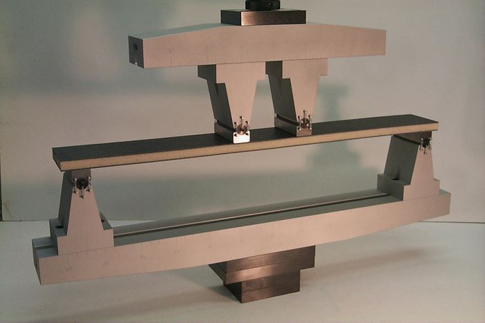
In contrast, the standard test for core shear properties determinations requires a three-point loading configuration, with only a 150-mm/6-inch support span. This "short beam"specimen is 200 mm/8 inches long, but is still 75 mm/3 inches wide. Therefore, if a single test fixture is to be used for all sandwich panel testing, it must have a minimum width of 75 mm/3 inches; three-point and four-point loading capability; and either fixed spans of the dimensions noted above or adjustable spans. Fortunately, this is not too difficult to achieve. Fig. 1 shows a fixture that meets these conditions. It is shown configured for four-point loading, but when three-point loading is required, one loading head can be removed and the remaining head can be moved to the center of the loading beam. This particular fixture has a maximum support span of 610 mm/24 inches, which is more than required by the standard tests described above, but the full span may be required for nonstandard tests. Since both the loading and support spans are fully adjustable, this fixture can readily accommodate other nonstandard test configurations as well.
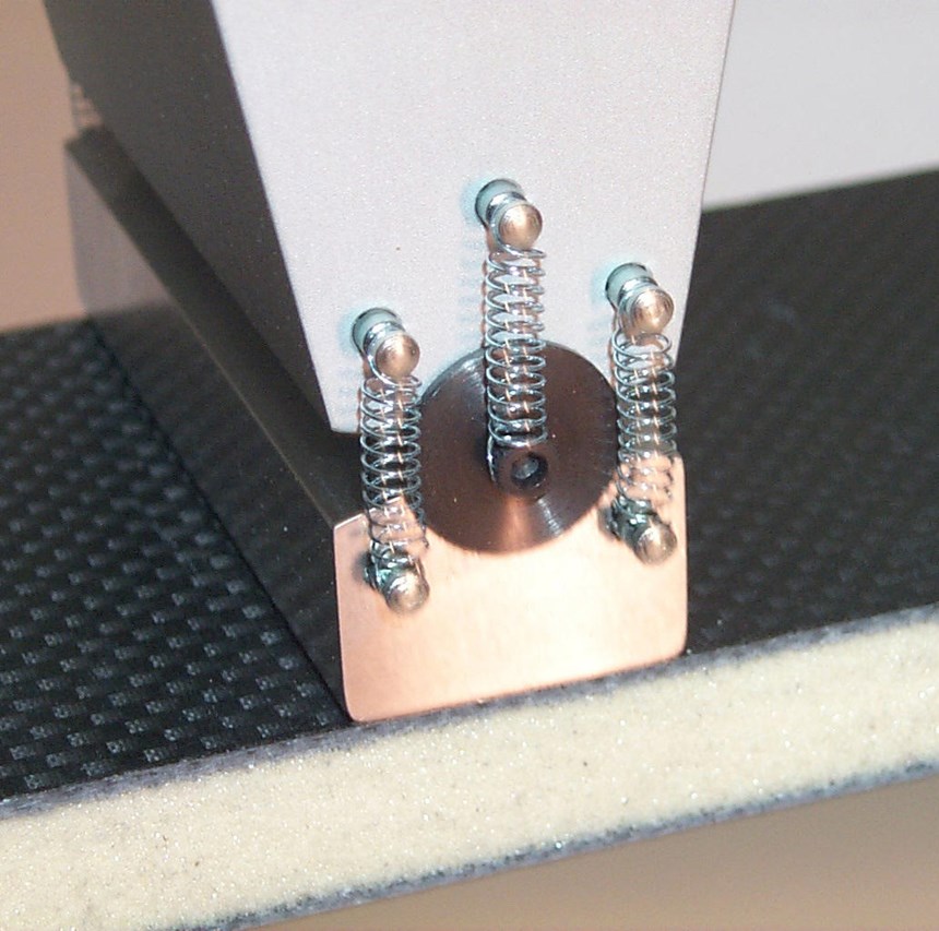
Fig. 2 is a close up of one of the loading pads on this fixture (the support pads and loading pads are identical). The hardened steel flat pad is free to rotate on the hardened steel cylinder, which permits free rotation of the specimen when the specimen deflects under load, as required in the ASTM standards discussed above.
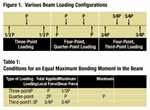
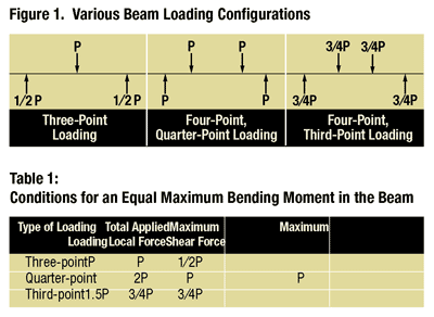
A noteworthy feature of the ASTM standard test configuration for facesheet properties determination is the four-point loading span of 100 mm/4 inches. For flexure testing of solid laminates rather than sandwich panels (see "Flexure test methods," under Editor's Picks"), the loading span is typically either 1/2 (termed quarter-point loading) or 1/3 (termed third-point loading) the length of the support span. In contrast, the loading span for the sandwich panel long-beam flexure test method discussed here is only 1/5.5 of the support span. That is, the two loading points are considerably closer together than for either quarter-point or third-point loading. In the November article, I discussed in detail the advantages of moving the loading points closer together when conducting any four-point loading flexure test, and the standard ASTM sandwich panel facesheet properties test configuration incorporates this favorable configuration.
In contrast to flexure-testing sandwich panels, when testing solid laminates the support and loading cylinders usually have relatively small diameters, i.e., 6 mm to 10 mm (0.25 inch to 0.39 inch). As discussed above, sandwich specimens are typically supported and loaded by means of 25-mm/1-inch wide flat plates. While the ASTM standards permit the use of 25-mm/1-inch diameter steel cylinders, it is noted that there is a greater risk of local specimen crushing because of the more concentrated loading induced by a cylinder. Any local crushing of the core under a facesheet, particularly the facesheet that is on the compression surface of the beam, is always a concern no matter which loading and support configurations are used. A locally deformed facesheet on the compression surface of a flexure specimen could fail prematurely by local bending or buckling. For this reason, the ASTM standards for sandwich panel testing specify not only flat support and loading surfaces but 3-mm/0.125-inch thick rubber pads between the support and loading flats and the specimen as well. This further relieves local stress concentrations and, thus, reduces the occurrence of local facesheet damage.
Finally, I noted earlier that ASTM defines standard specimen and loading configurations, but also permits nonstandard configurations. In fact, a nonstandard configuration could be required for flexure testing when the particular sandwich panel — short beam or long beam — does not meet certain criteria. These criteria include the required span length, core shear strength and core compression strength. Each criterion is defined as a function of the facesheet's expected ultimate strength, facesheet thickness, core thickness, core shear allowable strength, core compression allowable strength and even the width of the loading pads to be used. Appropriate formulas for evaluating these criteria are given in the standards.
The ASTM sandwich panel testing standards discussed here will be released when the current round of revisions is complete — a process I expect will take six months to one year. Users of the test methods should find them much easier to interpret and implement than methods defined in previous standards.
Related Content
Crashworthiness testing of composites: A building block approach, Part 1
Determining the crashworthiness of composite structures requires several levels of testing and analysis, starting with coupon-level crush testing.
Read MoreCrashworthiness testing of composites: A building block approach, Part 2
Following the previously discussed coupon-level testing element, subcomponent and component testing are the next steps in designing crashworthy composite structures.
Read MorePhotothermal tomography for locating, quantifying defects in composites
Years of infrared testing development result in thermography technology that is no longer just qualitative, but can define defect size and depth, making additional UT scans obsolete.
Read MoreDamage tolerance testing of sandwich composites: The sandwich CAI test
A new ASTM-standardized test method established in 2022 assesses the compression-loaded damage tolerance of sandwich composites.
Read MoreRead Next
Sandwich panel test methods
This column will introduce sandwich panel test methods in general. Detailed discussions of the individual test methods will be presented in future columns. Sandwich panels will be defined here as those consisting of relatively thin facesheets that are strong and stiff in tension and compression compared to the low
Read MoreFlexure test methods
The three fundamental mechanical property characterization tests of materials are tension, compression and shear. Note that flexure is not included. This article addresses some of the reasons why. When a beam resting on supports near its ends is loaded, the supported side is in tension and the opposite side is in
Read MoreVIDEO: High-volume processing for fiberglass components
Cannon Ergos, a company specializing in high-ton presses and equipment for composites fabrication and plastics processing, displayed automotive and industrial components at CAMX 2024.
Read More

