
Commercialization of CMCs and developments for next-gen performance
As industrial production of parts begins, new developments offer promise for higher-temperature and more damage-tolerant ceramic matrix composite (CMCs).


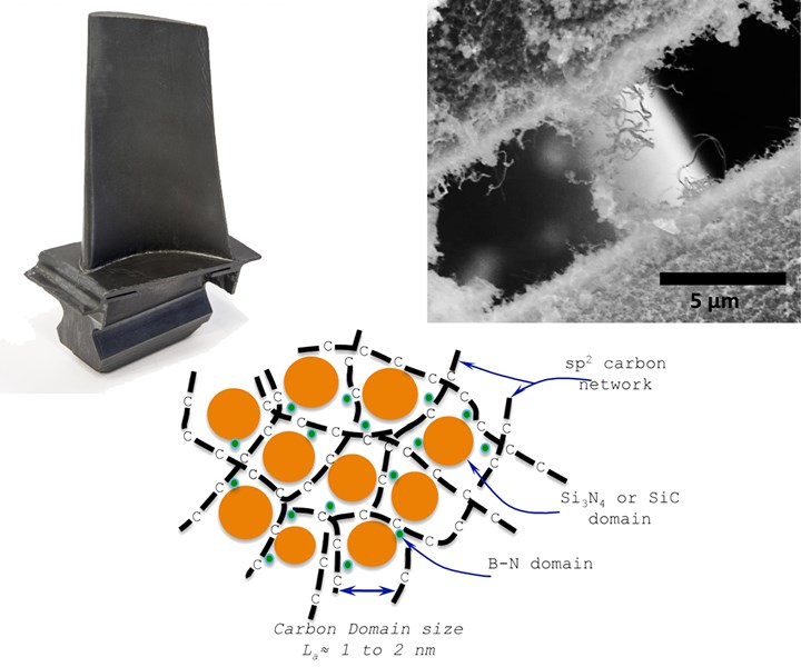
Next-generation ceramic matrix composites (CMCs) are being developed for future applications such as turbine blades (top left). These may use new technologies such as water-like polymers that can be processed into 1700°C-capable, low-density ceramics (bottom) or nanofibers grown onto silicon carbide (SiC) reinforcing fibers for increased toughness (top right). SOURCE | GE Reports, Kansas State University, Rice University
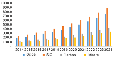
CMCs are projected to grow at a CAGR of 9.65% from 2016 to reach USD 7.51 billion by 2026. SOURCE: Markets and Markets, Grandview Research
Why is the use of ceramic matrix composites (CMCs) growing in applications such as jet aircraft engines and industrial turbines?


- CMCs are 1/3 the weight of previously used nickel (Ni) super-alloys.
- CMCs can operate at temperatures up to 500°F higher than Ni super-alloys.
- Higher service temps mean less cooling air is diverted from thrust, allowing engines to run at higher thrust and/or more efficiently.
- Engines also run hotter, combusting fuel more completely, reducing fuel consumption and emissions.
- Similarly, CMCs in industrial power turbines could reduce environmental pollution and the cost of electricity.
The graphs below show how CMCs outperform previous aeroengine materials like the Ni super-alloy Inconel. The silicon carbide (SiC) fiber reinforced/SiC matrix (SiC/SiC) composites being mass-produced by GE Aviation (Evendale, Ohio, U.S.) operate at 2400°F (1316°C). The bottom graph shows one view of where future CMCs are headed in terms of temperature.
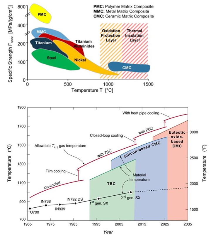
CMCs offer higher temperature cability compared to previously-favored metals such as Titanium and Nickel (top graph) and alloys such as Inconel (e.g., IN738, IN939 and IN792 DS in bottom graph). SOURCE | (top) “Turbomachinery components manufacture …,” by Fritz Kocke, et. al. via ScienceDirect.com (bottom) Wadley Research Group, Univ. of Virginia
GE Aviation has spent more than $1.5 billion over the past decade to bring this technology to market. When finished, the supply chain it will have constructed includes:
- A CMC laboratory in Evendale
- A low-rate production facility in Newark, Del.
- A full-rate production facility in Asheville, N.C. to mass-produce CMC parts, including static turbine shrouds, for CFM LEAP engines
- A full-rate raw material production facility in Huntsville, Ala.

Process chain for SiC fiber-reinforced SiC matrix composites. The final step is melt infiltration (MI) of liquid silicon into the carbonized composite preform to form the densified SiC/SiC ceramic composite. SOURCE| CW, note that icons are not meant to show realistic detail but instead to visualize steps in a generalized process.
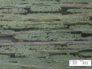
Optical microscope image of a SiC/SiC composite showing woven fiber bundles reinforcing the matrix. SOURCE | Nicholas Simos, intechopen.com
According to a July 2016 GE Reports article by Tomas Kellner, GE Aviationfirst CMCs in the hot section shrouds of its F136 fighter jet engine. In 2015, GE started testing CMC components in a GEnx engine (used on the 787 Boeing Dreamliner) to mature the technology for the GE9X — the largest jet engine ever built with a fan diameter of 11 feet — which will power the Boeing 777X jetliner.
CMC parts are already flying in the LEAP engine used on the Boeing 737 MAX, Airbus A320neo and COMAC C919 jets. The LEAP engine is manufactured by CFM International (Cincinatti, Ohio, U.S.) — a 50/50 joint venture between GE Aviation and Safran Aircraft Engines (Courcouronnes, France)
Next-gen CMC Development
According to an article by Dawn Levy at Oak Ridge National Laboratory (ORNL, Oak Ridge, TN US), the U.S. Advanced Ceramics Association (Washington, DC, US) is developing a road map for 2700°F (1482°C) CMCs. "This is going to be as challenging as the development of the first ceramic composite," says Krishan Luthra, who led CMC development at GE Global Research for 25 years. "Every decade we have increased [the heat metals can take] by about 50 degrees.”
Continuing in Levy’s article, Luthra’s vision is to extend CMCs throughout the hot zone of jet engine and industrial power turbines, including blades, nozzles and liners.
In fact, the GE9X, GE’s replacement for its GE90 engine powering Boeing’s 777, will incorporate five different types of CMC parts — inner and outer combustor liners and high pressure turbine (HPT) Stage 1 shrouds, Stage 1 nozzles and Stage 2 nozzles — when the 777X enters service in 2019. This is a significant expansion from just the HPT Stage 1 shrouds in the LEAP engine, which is the first widely deployed CMC-containing product and is now ramping in production to >2,000 engines (36,000 shrouds) per year by 2020. There are >700 orders for the GE9X vs. >12,200 orders for the LEAP engine.
As CMCs push forward, one challenge, according to Levy, is developing manufacturing processes that, unlike the melt infiltration (MI) process used by GE, will not produce excess silicon that can volatilize and form cracks in the matrix. Another issue, highlighted in a ceramicindustry.com article, is that materials containing silicon are subject to material loss at high temperature due to a reaction with water vapor. This recession is a known chemical reaction that is currently mitigated by a multi-layer environmental barrier coating (EBC). The cost of CMCs could be reduced if the need for this coating could be reduced or eliminated.
Water-like Polymer
Newly patented polymer may offer a route for higher-temp CMCs. SOURCE | Kansas State University.
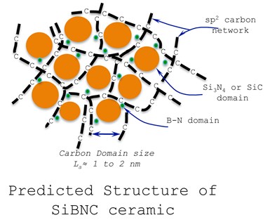
Kansas State University (Manhattan, KS, US) researchers Gurpreet Singh, Harold O. and Jane C. Massey Neff have developed a polymer with density and viscosity similar to water that can be processed into a 1700°C-capable ceramic with a mass density 3-6 times lower than that of other ultrahigh-temperature ceramics, such as zirconium boride and hafnium carbide. The ceramic derived from this polymer has a random structure that is generally not observed in traditional ceramics: the silicon bonds to nitrogen and carbon but not boron; boron bonds to nitrogen but not carbon; and carbon bonds to another carbon to form graphene-like strings. This unique structure provides stability at high temperatures by delaying reaction with oxygen.
Made from five ingredients — silicon, boron, carbon, nitrogen and hydrogen — this patented polymer has a longer shelf life than other SiBNC polymers, but with heat is transformed into a very black, glasslike ceramic.
It can also be used to make ceramic fibers. When heated to ≈50-100°C, the polymer becomes a syrupy gel that can be pulled into filaments to create ceramic textiles or mesh. It can also be poured into molds and heated to make high-precision, complex ceramic shapes. Other modes of processing flexibility include a sprayable coating for high-temp protection and use in 3D printing.
Combined with carbon nanotubes, the resulting black material can absorb all light — even ultraviolet and infrared light — without being damaged and is able to withstand extreme heat of 15,000 watts/cm2 or roughly 10 times more than a rocket nozzle.
Sic Fuzzy Fibers Act Like Velcro
Protection against high-temp oxygen corrosion
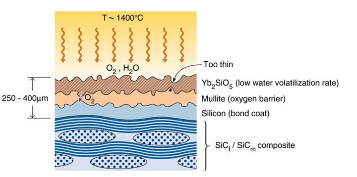
The architecture of a candidate environmental barrier coating (EBC) system for protecting SiC-based CMC parts. SOURCE | Fig. 2, Environmental Barrier Coatings, Wadley Research Group, Univ. of Virginia.
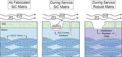
The concept of self-healing matrix materials that can form a protective scale similar to an EBC has been demonstrated. SOURCE | David Poerschke, Univ. of California Santa Barbara (UCSB).
CMC parts in rocket engines must withstand 1600°C temperatures and can crack or become brittle when exposed to oxygen. For this reason, they are treated with a thermal or environmental barrier coating (TBC or EBC), which is an expensive and time-consuming additional step. Thus, researchers continue to look for ways to improve CMC abilities to resist damage-forming mechanisms.
Rice University’s (Houston, TX, US) Department of Materials Science and NanoEngineering (MSNE) began working with NASA to explore how nanotubes could improve SiC-based CMC damage tolerance. In the Rice Universtiy MSNE research lab headed by Pulickel Ajayan, SiC nanotubes and nanowires were embedded into the surface of NASA-supplied SiC fibers. The result is a nanoscale Velcro, where the exposed parts of the fibers are curly and act like hooks and loops, creating very strong interlocking connections where the fibers tangle. This not only makes the composite less prone to cracking but also seals it to prevent oxygen from changing the fiber’s chemical composition.
The work began when Rice graduate student Amelia Hart, who had been studying the growth of carbon nanotubes (CNTs) on ceramic wool, met Michael Meador, then a scientist at NASA’s Glenn Research Center (Cleveland, OH, US). Meador is now nanotechnology project manager at NASA’s Game Changing Technologies program. An ensuing fellowship in Cleveland allowed Hart to combine her ideas with those of NASA research engineer and pap grow nanotubes and figured out how to make the new coer co-author Janet Hurst. “She was partially converting silicon carbide from carbon nanotubes,” Hart said. “We used her formulation and my ability tomposite.”
Back at Rice, Hart and her colleagues grew their hooks and loops by bathing SiC fiber in an iron catalyst and then using water-assisted chemical vapor deposition (CVD) to embed a carpet of CNTs directly into the surface. The fibers were then heated in silicon nanopowder at high temperature, which converts the CNTs to SiC “fuzz.”
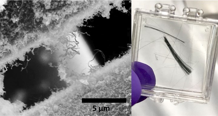
SiC “fuzz” grown from carbon nanotubes onto SiC fibers provide very strong interlocking connections that may boost damage tolerance for SiC-based CMCs. SOURCE | Rice University, Ajayan Research Group.
In friction and compression tests, the lateral force needed to move SiC nanotubes and wires over each other was much greater than that needed to slide past either plain nanotubes or unenhanced fibers. SiC nanotubes were also able to easily bounce back from high compression applied with a nano-indenter, demonstrating their ability to resist breaking down for longer amounts of time.
Tests to see how well the fibers handled heat showed plain CNTs burning away from the SiC fibers, while the SiC nanotubes easily resisted temperatures of up to 1,000°C. Hart now plans to apply her conversion techniques to other carbon nanomaterials to create unique 3D materials for additional applications.


Related Content

Raw materials distributor provides quality fiberglass, resin variety
CAMX 2024: Imate Composites presents a variety of resins, fiberglass and roving products, as well as mats and catalysts.
Read More
JEC World 2024 highlights: Thermoplastic composites, CMC and novel processes
CW senior technical editor Ginger Gardiner discusses some of the developments and demonstrators shown at the industry’s largest composites exhibition and conference.
Read More
“Structured air” TPS safeguards composite structures
Powered by an 85% air/15% pure polyimide aerogel, Blueshift’s novel material system protects structures during transient thermal events from -200°C to beyond 2400°C for rockets, battery boxes and more.
Read More
Hexcel introduces mid-temp Flex-Core HRH-302 honeycomb core
Bismaleimide (BMI) option to serve complex curvatures and thermal management needs of military, commercial and UAM aircraft.
Read MoreRead Next

VIDEO: High-volume processing for fiberglass components
Cannon Ergos, a company specializing in high-ton presses and equipment for composites fabrication and plastics processing, displayed automotive and industrial components at CAMX 2024.
Read More
Developing bonded composite repair for ships, offshore units
Bureau Veritas and industry partners issue guidelines and pave the way for certification via StrengthBond Offshore project.
Read More
Plant tour: Daher Shap’in TechCenter and composites production plant, Saint-Aignan-de-Grandlieu, France
Co-located R&D and production advance OOA thermosets, thermoplastics, welding, recycling and digital technologies for faster processing and certification of lighter, more sustainable composites.
Read More