Thermoplastic composites save weight in rotorcraft aerostructure
This helicopter structure outdoes both metal and thermoset-composite alternatives.
Design Results:
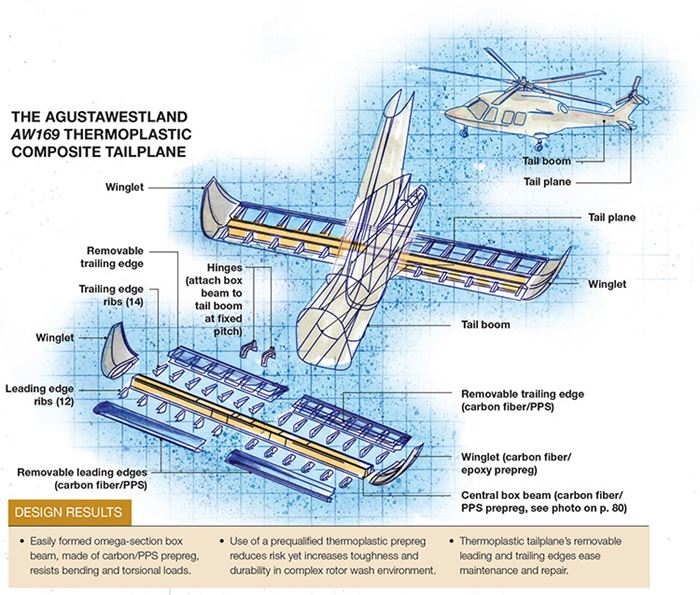
• Easily formed omega-section box beam, made of carbon/PPS prepreg, resists bending and torsional loads.
• Use of a prequalified thermoplastic prepreg reduces risk yet increases toughness and durability in complex rotor wash environment.
• Thermoplastic tailplane’s removable leading and trailing edges ease maintenance and repair.
Aircraft designers juggle goals that often seem mutually exclusive: They must keep risk low, yet implement new, lightweight and innovative technologies. The latter typically requires the use of not-yet-qualified materials. This is a particularly difficult challenge for builders of helicopters, who contend with aerodynamic loads that are more complex than those for fixed-wing aircraft. The adoption of new materials and structures is especially challenging, because the additional load cases complicate the predictive design process.
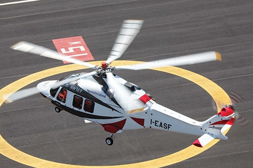
All the more newsworthy, then, is the fact that AgustaWestland (Cascina Costa di Samarate, Italy) recently struck what has proven to be a beneficial balance between risk management and innovation, says Michael Overd, head of structures design and development at AgustaWestland, in the design of the horizontal tailplane (HTP) for the company’s newest model, the AW169.
Designed and manufactured by Fokker Aerostructures (Papendrecht, The Netherlands) to AgustaWestland performance specifications, the tailplane is a thermoplastic composite. Notably, it is the only thermoplastic aerostructure on the otherwise thermoset composites-intensive airframe. The twin-engine, 8- to 10-passenger, multirole, 4-metric-tonne-class commercial helicopter was already nearly 50 percent composites by weight. “We were looking for a high-technology solution, with minimal risk, that was lighter than conventional composites,” Overd notes, pointing out that the shift from a thermoset to a thermoplastic matrix was actually negotiated with a very manageable risk profile. “We’ve achieved an innovative design using already-qualified material.”
Assessing complex forces
Although AgustaWestland specified the required size, strength and aerodynamics of the part using proprietary design software and methods, the HTP’s design solution was the product of a collaborative, interactive effort between AgustaWestland and Fokker. “We actually began our collaboration with Fokker in 2010,” says Overd.
A key to flight stability, the HTP acts to keep the aircraft level by overcoming a pitching tendency during forward flight, Overd explains. That task is no simple matter in a helicopter’s complex flight environment. “The design problem is somewhat tricky,” he notes. “A designer has to consider the airfoil profile, chord and aspect ratio, the position on the tail, proximity to the tail rotor, if the HTP’s angle can be adjusted and so on, because each helicopter’s design is unique.”
A Sikorsky Black Hawk, for example, has a very large HTP with variable pitch that optimizes its stability during rapid military maneuvers. To illustrate just one of the complications involved with design of the HTP, Overd cites induced asymmetrical downward airflow created by the rotor’s counterclockwise rotation. The resulting downwash impacts a helicopter’s rear fuselage, tailboom and HTP. This can cause “tail shake,” a condition where aerodynamic buffeting excites a fundamental vibration mode in the airframe. “We needed an HTP design with good static strength and fatigue resistance to cope with the overall vibration environment,” says Overd.
And that is just one of the phenomena designers must address. “Helicopter design involves an interrelated set of problems,” Overd points out, “and dealing with one issue can exacerbate another.”
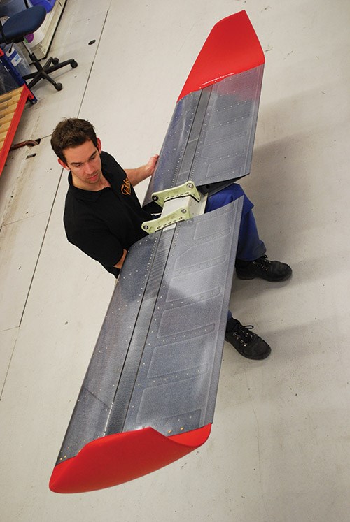
AgustaWestland developed an overall HTP shape, with a length of 3m/9.75 ft, a chord span of 0.62m/2 ft, and a depth (thickness) of 150 mm/6 inches. It has an asymmetrical airfoil — that is, the shapes of the leading and trailing edges are slightly different on the left and right sides, which Overd says was necessary to account for the asymmetrical flow field during flight. Further, the HTP was to be mounted in a fixed-pitch orientation below the tailfin, a position that would be finalized only after extensive flight testing. Finally, upward-curved winglets were specified for each end of the HTP.
Overd sought to manufacture the HTP using lightweight composites that could meet the modeled aerodynamic loads and performance requirements. Working with Arnt Offringa, director of R&D at Fokker Aerostructures, and Fokker’s chief engineer Cees Borsboom, he investigated a thermoplastic solution because Fokker had a long history with thermoplastics, notably on the Gulfstream G650 rudder and elevators. “We liked that Fokker had already designed certified thermoplastic structures on aircraft using thermoforming and welded stiffeners for weight reduction,” he says, ”and we believed a thermoplastic design would perform as well or better than thermoset materials, at a lower weight.”
That said, Offringa notes that the helicopter design environment was much different than what he had experienced with fixed-wing aircraft: “We had a very short time span in which to develop a material and manufacturing approach,” he recalls, adding that helicopter OEMs tend to prototype and test parts quickly because of the aforementioned complexities in predictive modeling. Nevertheless, he says there was one time saver: “Luckily, we had developed a robust beam concept for thermoplastic floor panels in transport aircraft that we believed could be adapted to this project.”
Thermoplastic primary structure
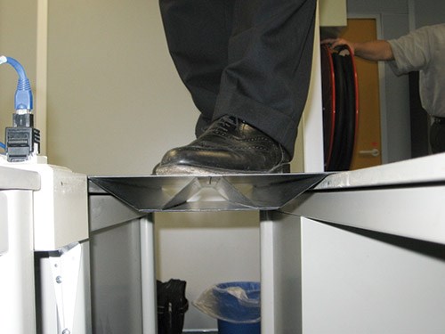
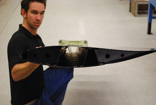
The floor panel idea consisted of two “omega” sections (that is, profiles that roughly resemble the Greek letter Ω) butted together between flat skins. The result is a flat panel, a prototype of which is shown in the photo above, supporting a man’s weight with virtually no deflection. Using CATIA software from Dassault Systèmes (Vélizy-Villacoublay, France), Offringa and his team modified the concept with deeper omega sections, using carbon fiber/polyphenylene sulfide (PPS) prepreg, preformed to fit the HTP’s shape, and produced a 3m/9.8-ft long beam with slightly curved plies above and below the omega sections to form box beam skins that could resist bending and torsional loads. The upper and lower skins, joined to the omega sections in a hot co-consolidation process, vary in thickness, with plies added near the beam’s centered attachment hinges for greater stiffness and torsion resistance.
Although a carbon fiber/polyetherketoneketone (PEKK) material was considered, Fokker chose instead to use carbon/PPS prepreg because it was already qualified on Airbus and Gulfstream business-jet programs (see “Learn More”). T300, 5-harness satin weave fabric prepreg was supplied by TenCate Advanced Composites (Nijverdal, The Netherlands). Made with carbon fibers from Toray Industries Inc. (Tokyo, Japan), the fabric was powder-coated with Fortron PPS, supplied by Celanese Corp. (Dallas, Texas and Sulzbach am Taunus, Germany).
A stepped, box-like forming tool, developed by Fokker, not only accommodated the box beam skin ply drop-offs but also had removable mandrels that fit inside and maintained the “omega” shapes during melting and cooling steps. Reportedly, the tool enabled beam formation in a single step, in a matter of minutes.
AgustaWestland wanted a thermoplastic leading edge for impact performance, and wanted to be able to remove the leading and trailing edges so that they could be replaced in service if damaged. In line with that directive, Fokker designed thin two-ply and three-ply (0.3 mm/0.012-inch thickness per ply) carbon/PPS skins using the same TenCate powder-coated fabric. These were supported by, and mechanically fastened to, equally thin, molded thermoplastic composite ribs, 12 for the leading-edge and 14 for the trailing-edge (shown in the drawing at top left), These are fastened to the beam with stainless steel rivets. Each rib has upper and lower flat flanges that accept rivets yet maintain the proper aero shape. Because the left- and right-side leading and trailing edges differ in shape, their skins are thermoformed in four separate tools. The layup, however, is the same for left and right sides. Offringa adds, “The 5-harness fabric is very drapeable, which helps us form the ribs and skins.”
Carbon/epoxy fabric prepreg from Hexcel (Stamford, Conn.) was specified for the winglets. Overd says his company had already developed the same solution for the existing AW139 model, and the additional process development for a thermoplastic winglet would have been very difficult in the time allowed, due to the part’s double-curvature “glove” shape and thin skin: “It was a question of diminishing returns to pursue thermoplastics, because of the tooling cost and time. We opted to go with thermosets.” Winglets, made separately by Fokker, have attachment flanges that slip inside the HTP and accept mechanical fasteners.
To ensure the HTP would meet the modeled, and proprietary, load cases, FEA stress analysis of the design was undertaken by the Fokker design team using MSC Patran and MSC Nastran from MSC.Software (Santa Ana, Calif.). Borsboom says Fokker stress manuals, which contain thermoplastic composite allowables data, also were consulted and reports that favorable virtual tests led to static physical testing, which included bending of the beam to failure prior to the first flight of the first AW169 prototype.
Additional static and dynamic testing will occur this year during formal certification. Four AW169 prototypes are already flying. Flight tests, thus far, have shown that the HTP can withstand the vibration environment and exhaust temperatures, given a few ongoing design “tweaks” to the aircraft. Certification by the European Aviation Safety Agency (EASA) is expected sometime this year. Cross-filing with the U.S. Federal Aviation Admin. will follow thereafter.
“We’re happy with the impact-resistant thermoplastic solution,” says Overd, “and the fact that the spar can be produced in a one-shot process, without fasteners.”
Offringa adds, “We’ve achieved a solution that outperforms traditional materials at a significant weight savings” — 15 percent less than a conventional thermoset composite design.
“We definitely will consider using thermoplastic materials in future projects,” Overd concludes.
Related Content
Plant tour: Joby Aviation, Marina, Calif., U.S.
As the advanced air mobility market begins to take shape, market leader Joby Aviation works to industrialize composites manufacturing for its first-generation, composites-intensive, all-electric air taxi.
Read MorePEEK vs. PEKK vs. PAEK and continuous compression molding
Suppliers of thermoplastics and carbon fiber chime in regarding PEEK vs. PEKK, and now PAEK, as well as in-situ consolidation — the supply chain for thermoplastic tape composites continues to evolve.
Read MoreOptimizing a thermoplastic composite helicopter door hinge
9T Labs used Additive Fusion Technology to iterate CFRTP designs, fully exploit continuous fiber printing and outperform stainless steel and black metal designs in failure load and weight.
Read MoreJeep all-composite roof receivers achieve steel performance at low mass
Ultrashort carbon fiber/PPA replaces steel on rooftop brackets to hold Jeep soft tops, hardtops.
Read MoreRead Next
Thermoplastic composites: Primary structure?
Yes, advanced forms are in development, but has the technology progressed enough to make the business case?
Read MoreAll-recycled, needle-punched nonwoven CFRP slashes carbon footprint of Formula 2 seat
Dallara and Tenowo collaborate to produce a race-ready Formula 2 seat using recycled carbon fiber, reducing CO2 emissions by 97.5% compared to virgin materials.
Read MoreDeveloping bonded composite repair for ships, offshore units
Bureau Veritas and industry partners issue guidelines and pave the way for certification via StrengthBond Offshore project.
Read More

