Transverse flexure testing
Dr. Donald Adams examines test methods for determining the transverse tensile strength of a composite formed from unidirectional plies.
Many composite structures are fabricated from unidirectional composite plies oriented in various directions as necessary to carry applied loads. However, due to load transfer between plies, stresses transverse to the fiber orientation also are induced in each ply. Although the axial strengths, both tensile and compressive, of a unidirectional ply are typically very high, transverse strengths are not because they are matrix-dominated or interface-dominated. Further, the transverse tensile strength of a ply is typically only a fraction of the transverse compressive strength, because any local failure at a stress concentration in a tensile stress field will propagate as a crack, but will not do so in a compressive stress field. Often, this tensile crack is arrested when it reaches a ply interface, permitting continued loading of the laminate as ply cracks continue to propagate. Eventually, however, the fibers themselves can fail, dictating the final failure of the laminate.
Therefore, while both the transverse tensile strength and the transverse compressive strength of the unidirectional ply are of interest for design purposes, it is typically the transverse tensile strength that governs failure.
The issue, then, is how to measure the transverse tensile strength. A common approach is a simple transverse tensile test1 of a unidirectional composite (see Fig. 1a). However, this method is sensitive to crack propagation from local stress concentrations anywhere within the gage section, but especially at the gripped ends.
A related issue is how to measure the interfacial bond strength between the fiber and matrix. Many types of single-fiber tests exist, all of which require loading a single fiber while it is encapsulated in matrix material. But manipulating the single fibers is painstaking and time-consuming work, and the test results tend to be qualitative rather than quantitative, often showing considerable data scatter.
An attractive alternative is to test an actual composite. A short beam shear test of a unidirectional composite can be performed2, thus loading the interface primarily in shear (see end note). Or the transverse flexure test can be used, loading the interface primarily in tension. Either interfacial-loading mode can be the more significant of the two in an actual structure. This suggests that both tests should be performed.
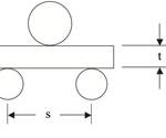
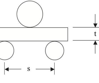
Interestingly, the two tests are similar in nature, equally simple to perform and use the same test setup. For short beam shear testing, the fibers are oriented along the length of the beam specimen. For transverse flexure testing they are oriented in the width direction of the beam, as indicated in Figs. 1b and 1c. In both cases, either three-point or four-point loading can be used.
For short beam shear testing, studies have shown no advantage in using four-point loading. Further, three-point loading is simpler to perform and permits the use of shorter specimens, thereby consuming less material.
Accordingly, three-point loading is the general standard2. Similar study findings favor three-point loading for transverse flexure testing as well, as discussed, for example, by O’Brien, et al.3,4.
Short beam shear and transverse flexure are both beam-bending tests. The specimens used in each are, therefore, subjected to complex stress states that combine a bending stress — which varies linearly from maximum compression at the concave surface to maximum tension at the convex surface — with an approximately parabolic interlaminar shear stress distribution that varies from zero at each surface to a maximum at the mid-thickness of the beam. For the short beam shear test, elementary beam theory predicts a maximum shear stress of 0.75 P/A, where P is the applied force and A is the cross-sectional area of the beam. Note that this shear stress is independent of the support span length of the beam. However, because the tensile and compressive stresses increase as the span length increases, the span length is kept small to promote a shear failure. For example, ASTM D 23442 specifies a support span length-to-specimen thickness ratio (s/t) of 4.
For the transverse flexure test, the maximum tensile (and compressive) stress is 1.5 (s/t) P/A. Thus, even at an s/t ratio of only 4, the transverse tensile stress is eight times the shear stress. Since, as noted earlier, the transverse tensile strength is typically less than the shear strength, a tensile failure is assured in the transverse flexure test.
With the goal of identifying an accurate transverse tensile test for a unidirectional composite, Adams, et al.5, compared results obtained using the transverse tensile test (Fig. 1a) and the three-point loading transverse flexure test (Fig. 1b). This study indicated that the transverse tensile test produces significantly lower values, suggesting that induced stress concentrations have a greater influence, because a much larger volume of material is subjected to the maximum stress. A severe flaw anywhere within the gage section of a transverse tensile specimen can induce total failure.
By contrast, in the three-point transverse flexure test, only the surface on the convex side at mid-span on the loaded specimen is at the maximum stress level. This stressed-volume effect also has been demonstrated by comparing transverse flexure results for three-point and four-point loading3,4. In tests that use four-point loading, the entire convex surface of the specimen between loading points is subjected to the maximum tensile stress, thus increasing the probability of a critical flaw. Correspondingly, O’Brien, et al.3,4, noted a small reduction in measured transverse flexural strength.
That transverse tensile strength is flaw-sensitive is further demonstrated by the fact that transverse flexure failures in three-point bending tests do not regularly occur at the loading point, where the tensile stress is greatest, but instead typically occur randomly on either side at short distances from the loading point.
Indications are that these flaws are inherent in the material rather than introduced during specimen preparation. For example, O’Brien, et al.3,4, very carefully polished both the edges and the tensile surface of some specimens before transverse flexural testing. These specimens exhibited strengths no higher than the others. Likewise, strength variations as a function of specimen length, width and thickness were minimal.
In summary, the transverse flexural test of a unidirectional composite should be given more attention, both as an attractive alternative to the transverse tensile test when determining basic ply properties and as a method for evaluating fiber-matrix interfacial bond strength.
Read Dr. Adams’ discussion of "The short beam sheat test" for unidirectional composites under "Editor's Picks," at right.
References
1ASTM D 3039-00, “Tensile Properties of Polymer Matrix Composite Materials,” ASTM International (W. Conshohocken, Pa.), originally issued in 1971; re-approved 2006.
2ASTM D 2344-00, “Short-Beam Strength of Polymer Matrix Composite Materials and Their Laminates,” ASTM International (W. Conshohocken, Pa.), originally issued in 1965; re-approved 2006.
3T.K. O’Brien, A.D. Chawan, K. DeMarco, and I. Paris, “Influence of Specimen Configuration and Size on Composite Transverse Tensile Strength and Scatter Measured Through Flexure Testing, Journal of Composites Technology & Research, Vol. 25, No. 1, 2003, pp. 3-21.
4T.K. O’Brien, A.D. Chawan, R. Krueger, and I. Paris, “Transverse Tension Fatigue Life Characterization Through Flexure Testing of Composite Materials, NASA TM-2001-211035, NASA-Langley Research Center (Hampton, Va.), July 2001.
5D.F. Adams, T.R. King, and D.M. Blackketter, “Evaluation of the Transverse Flexure Test Method for Composite Materials,” Composites Science and Technology, Vol. 39, No. 4., 1990, pp. 341-353.
Related Content
Damage tolerance testing of sandwich composites: The sandwich CAI test
A new ASTM-standardized test method established in 2022 assesses the compression-loaded damage tolerance of sandwich composites.
Read MoreCrashworthiness testing of composites: A building block approach, Part 2
Following the previously discussed coupon-level testing element, subcomponent and component testing are the next steps in designing crashworthy composite structures.
Read MoreTesting to support composite bolted joint analysis
An overview of ASTM Standard Guide D8509, and its coupon-level mechanical testing of design properties for analyzing composite bolted joints.
Read MoreCrashworthiness testing of composites: A building block approach, Part 1
Determining the crashworthiness of composite structures requires several levels of testing and analysis, starting with coupon-level crush testing.
Read MoreRead Next
The short beam shear test
Dr. Don Adams (Wyoming Test Fixtures Inc., Salt Lake City, Utah) discusses short beam shear testing methodology.
Read MorePlant tour: Daher Shap’in TechCenter and composites production plant, Saint-Aignan-de-Grandlieu, France
Co-located R&D and production advance OOA thermosets, thermoplastics, welding, recycling and digital technologies for faster processing and certification of lighter, more sustainable composites.
Read MoreVIDEO: High-volume processing for fiberglass components
Cannon Ergos, a company specializing in high-ton presses and equipment for composites fabrication and plastics processing, displayed automotive and industrial components at CAMX 2024.
Read More


