Why Microstructure Matters
Microtesting composite materials speeds seleMicrotesting composite materials speeds selection, allowing designers to consider more possibilities.ction, allowing designers to consider more possibilities.
Material testing and characterization is essential to designers and fabricators of aerospace composite components, but it also is time-consuming and the production of coupons and partial- or full-scale structures for validation can be prohibitively costly. Moreover, the inconvenience of producing additional sets of coupons and structures for retesting purposes often inhibits materials engineers from tweaking materials along the way to optimize properties. As a result, designers select often less-than-ideal but previously characterized composite formu-lations, and parts must be significantly over-designed to provide a safety margin that makes up for lack of confidence in the material's performance. Fortunately, the great cost of the materials testing cycle has prompted research into the cycle itself, aimed at developing methods and strategies that make it more efficient.
One result is the practice of microtesting. Researchers are finding that the critical information derived from conventional and often elaborate procedures that employ test coupons and full structures also can be derived from far simpler procedures that measure microscopic properties, using small test specimens. Even better, computer modeling of these microscopic properties is moving material characterization into the virtual world, significantly reducing physical testing requirements.
Microscopic testing and modeling hinges on the ability to correlate microscopic properties to full-scale performance parameters — a correlation that composites engineers are beginning to establish. The result of their work has been greater integration of material engineering, structural design, and man-ufacturing efforts; a greater breadth of material properties and property com-binations available to designers; and end products better tailored for both manufacture and operational demands.
Microstructural inroads
Microtesting has become common at prime contractors over the past couple of decades, says Don Uhlir, Raytheon Missile Systems' (Tucson, Ariz.) technical director, because it is a quick, relatively inexpensive ways of confirming that materials fall within design tolerances. As the following demonstrate, this "small" step can yield great benefits.
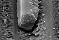
When Raytheon preselects materials and processes prior to accelerated aging tests, the company now checks the effect of environmental exposure on a potential material system by performing a single-fiber pullout test to qualitatively characterize the interfacial properties between the resin and the reinforcement's sizing (the coating on fibers that serves both as protection and as a coupling agent). This test replaces previous testing that required dozens of tensile and shear test specimens, which had to be aged for weeks or even months prior to testing. Fiber/resin pullout samples reach environmental equilibrium in days.
Single-fiber pullout testing is performed on a mini-tensile tester. A bead of resin is applied to a single fiber or tow and cured. A gripping device in the test equipment holds the resin bead, and the fiber is pulled under accurately measured tensile loading until debonding occurs. At this point, the equipment detects the interfacial friction as the fiber pulls through the bead. (If this force is not detected, fiber breakage may have occurred, and the test must be repeated.) For Raytheon's purposes, long-term moisture exposure is simulated by placing the cured bead and fiber in 100 percent humidity until weight gain equilibrium is reached. Data from the new system under investigation then can be correlated to the performance of previously characterized material systems.
Several companies offer mini-tensile testers. (Uhlir emphasizes that Raytheon does not endorse a particular vendor.) A number of instruments from Instron (Canton, Mass.) can be used for tensile testing of small test specimens, including the company's model 5848 MicroTester material testing system. This unit provides precise load and displacement measurement capability, Instron reports, offering position measurement resolution of better than 20 nm. The instrument reportedly applies force ranging from less than 0.002N to 2,000N (0.007 lbf to 448 lbf), with mea-surement accuracy of ±0.5 percent or better.
MTS Systems Corp. (Eden Prairie, Minn.) targets the microforce range of testing with its Tytron 250 system, with a load capacity from 0.001N to 250N (0.0002 lbf to 56 lbf). It can be fitted with an optical microscope to permit specimen observation during the test. Shimadzu Scientific Instruments (Columbia, Md.) recently entered this market with its Micro Autograph MST-I microstrain tester. The system employs a high-accuracy linear sensor (±0.2 microns) to measure dis-placements in the load direction with a displacement-display resolution of 0.02 microns. It offers load cells from 0.5N to 2,000N (0.112 lbf to 448 lbf) and the company guarantees accuracy within ±1 percent in measurements of forces above 0.002N (0.007 lbf). An optional stereo-microscope enables users to observe the test specimen directly.
Uhlir points out that gripping the specimen properly is critical. If mishandled, he notes, "It can be a significant cause of frustration and data scatter." Self-aligning lever-action grips work for the resin bead and larger fibers, and O-ring grips must be used for smaller fibers. "Special care is required to make sure the loading is 100 percent axial with O-ring gripping fixtures," he cautions.
Raytheon also uses a microindenting technique to reduce the number of test specimens the company must submit for expensive rain and erosion tests. The technique assesses the impact resistance of critical missile surfaces, such as wing leading edges. "Low fiber volume is a concern in these thin structures," Uhlir explains. "We need to know the rain- and sand-erosion properties, but there is only one real rain-erosion test facility in the country." It is located at the U.S. Air Force Research Laboratories, Wright-Patterson AFB, Ohio. (While erosion testing also can be done on a rocket sled track, it is more costly and harder to schedule.) Micro-indentation data correlates to an edge's erosion properties, because it indicates the material's small-impact resistance. Raytheon then can pretest a number of materials relatively quickly and place only the material with the best results into the queue at Wright labs.
Microindentation tests can be performed on composites with standard microhardness testers used in metallurgy, but Uhlir reports, "The data is not quantitative, since the rate the force is applied is not that of the environment that the part would actually be experiencing in flight." To perform the test, the force applied by the microhardness tester is held constant and multiple indentations are made with the goal of testing both resin-rich and high-fiber volume areas. A microscope, preferably with image analysis software, then records the removal or displacement of material by the indenter. As with microtensile tests, the indenter data is compared to known material systems that have been tested in certified rain or sand erosion facilities to gain a qualitative ranking of the material system.
Wilson Instruments (Norwood, Mass.), a business unit of Instron, offers the Tukon 2100B tester for micro-indentation tests. Test force range is from 0.1N to 10N. MTS offers several "nano-indenters" through its nanoinstruments division. The NanoIndenter XPW, for example, is designed to characterize surfaces down to a few nanometers. It makes controlled indentations with a diamond indenter tip. Shimadzu offers the DUH-201 Dynamic Ultra Micro Hardness Tester for low test forces (0.1mN to 1,960 mN), with a test force accuracy of ±1 percent.
Failure analysis is another key area where microstructural characterization has become a staple tool. In destructive analysis, test engineers analyze the degree of microcracking that occurred in a test coupon or structure prior to failure. "Components for which toughness is critical will have a lot of microcracking before failure," Uhlir clarifies, "while materials for which you want ultimate strength should have relatively little microcracking."
Scanning electron microscopes (SEMs) provide the images used for microcracking inspection. Electron microscopes work similarly to light microscopes except that electrons produce the images rather than photons. In SEMs, the specimen is placed under vacuum, and a beam of electrons, focused through several lenses, impacts the specimen and produces the electrons that are detected to make the image. Some of these electrons are backscattered from the original beam, while others are secondary electrons excited and released from the sample. "Scanning" designates the method of image production: the electron beam scans the surface in a manner similar to the movement of a television signal across a screen. Major manufacturers of SEMs include Carl Zeiss MicroImaging Inc. (Thornwood, N.Y.), Oxford Instruments Plc (Oxon, U.K.), JEOL Ltd. (Tokyo, Japan) and Hitachi Science Systems Ltd. (Ibaraki, Japan).
Trends and tailoring
While these techniques are not, according to Uhlir, "earthshaking discoveries" they are a big breakthrough in time/cost management. "They don't make a huge leap in material characterization, but they give us better confidence in selecting material systems that might meet long-term property requirements." Application of micro-structural testing is gradually broad- ening to help designers choose among more candidate materials, while trimming the volume of coupon-level and full design-level test requirements.
Uhlir cites trade studies as one of the arenas where microstructural testing is improving the material selection process. Single-fiber pullout, micro-indenting and SEM inspection can uncover trends within the data for a range of material formulations. Engineers might fine-tune the material formulation with small modifications of sizing, fiber volume, resin additives and so on, to develop a data curve. Then coupon-level testing with standard ASTM procedures can be used to hone in on a much smaller subset of formulations. Instead of selecting from among only those formulations tested at the coupon level, designers can see the correlation between microtests and coupon tests, and select a formulation tailored for the particular application being designed. Uhlir contrasts this use of microtesting with the broad-based testing that a prepreg vendor might perform to establish "B-basis" design allowables. A vendor wants to fully characterize its stock formulations for sale into many applications. On the other hand, a component designer wants a formulation tailored to a single application.
The advent of liquid crystal polymers (LCPs) for matrix-resin applications was a product debut tailor-made for tailored microtesting. "The microstructure in the resin gives us clues about the end product's total structural performance, whether it is brittle or tough," Uhlir explains. "This is especially important if we are using fillers in the LCP." Three test procedures can be used to help characterize an LCP's crystallinity: In the first, Uhlir uses SEM after etching. Etching is more commonly used to burn out a resin and determine fiber volume, but a shorter etching cycle preferentially etches non-crystalline portions of the LCP and brings out its crystalline structure. This permits viewing of the structure via SEM. The second method is cross-polarized reflected light microscopy, which metallurgists use to look at the grain structure of a metal. Used to observe polarizing effects of features within a composite sample, this method indirectly shows micro-structural order via extinction contours formed by the polarizers. Third, X-ray crystallography can determine the extent of crystallinity within a sample.
Potential for qualification and certification?
Historically, the process required to develop and then qualify a new composite material for commercial use in an aerospace component has been known to take 15 years or more. Little wonder, then, that contractors often select tried-and-true but less than ideal materials instead of newer, better, but as yet unqualified solutions. The long process has tended to discourage new materials development. Research that does go forward is typically aimed at general design parameters, rather than specific applications, since it is unlikely that the new material will be ready within any current program's design window.
While microstructural tests now enable designers to narrow the field of candidate materials, the materials ultimately must be submitted to full-scale testing, so researchers are envisioning the next logical step: radically reducing the need for physical testing, full-scale and microstructural.
"What if we had the capability, both structurally and from a materials standpoint, to predict performance at the micro level, simulate the composite's constituents, and predict the performance all the way up to the end product prior to physical testing?" asks Jerry Young, director of materials and process for Boeing Phantom Works (Seattle, Wash.). In this ideal situation, physical tests would only be needed to confirm and validate the data predicted in the models. While this is a distant goal, scientists are making progress toward better microstructural computer modeling, as well as links between that modeling and full-scale performance characteristics, which are likely to continue reducing physical tests.
Such modeling is one piece of the Accelerated Insertion of Materials —Composites (AIM-C) program. Funded by the Defense Sciences Office of the Defense Advanced Research Projects Agency (DARPA, Arlington, Va.) under the administration of NAVAIR and jointly carried out by a Boeing-led team and governmental partners, AIM-C has evaluated historical roadblocks to the implementation of new composite materials and has developed strategies and software tools to overcome those roadblocks.
AIM-C researchers say the key impediment to new materials insertion is the disconnect between materials development and design functions. The traditional process employs unlinked, sequential studies of (1) material properties, (2) material processing, (3) part manufacturing and yield, (4) performance and reliability in the specific application and (5) designer needs regarding cost, component life and so on. Understanding material properties traditionally has been an intensively empirical process that generates information not clearly related to scaled-up performance and reliability, even when computer modeling of those material properties has been generated. For example, molecular dynamics models, now being created at university research centers, allow researchers to predict how a resin's modulus changes as the quantity of a particular component is adjusted. But relating this change to the resin's pot life, the interfacial properties with a particular reinforcement, interlaminar properties, the ultimate strength of the scaled-up component, and the final component's life expectancy, requires the researcher to take the data from that modeling program and either sequentially plug it in to other computer modeling programs, or use the data to devise a round of physical tests.
Integration of some steps has certainly begun, Young points out. Computer modeling today typically takes designers from coupon test data to an end-product design, linking laminate behavior to finite-element analysis programs. Concerted efforts toward seamless integration of modeling are under way. For example, Dassault Systemes (Auburn Hills, Mich.), maker of CATIA V5 CAD software, has created a Software Community Program (SCP). Specific to composites design, SCP includes partners MSC.Software Corp. (Santa Ana, Calif.), provider of MSC.Patran and MSC.Nastran laminate modeling and analysis tools, and Magestic Systems Inc.'s (Old Tappan, N.J.) TruNEST nesting software and TruLASER View laser projection solution. SCP reportedly brings together an integrated package for 3-D conception, design, manufacture and maintenance of composite components.
While there has been much integration at the laminate level, there has been little done to bridge gaps as models progress from molecular dynamics to fiber-resin interaction, to laminate behavior. It still takes a number of discrete steps for which there is little in the way of software interface. To integrate constituent modeling and laminate modeling, software supplier VISTAGY Inc. (Waltham, Mass.) is sponsoring efforts at universities to model composite constituents, and foresees future integration with its software, which begins at the laminate level.
Linking the models is more than just a software problem; the scale-up from molecular dynamics to component performance must be accurately predictive. "Historically, the greatest effort is devoted to fixing problems," points out Gail Hahn, Boeing's AIM-C project manager, "because the capabilities and variabilities of the materials, processes, and design are not well understood in the manufacturing environment or in the operating environment over the lifetime of the application." In addition to making the models more accurate, another essential strategy is to identify robust portions of critical data curves. Researchers are developing techniques to understand constituent properties and end-product properties with consideration of manufacturing process and application environment variations. Young illu-strates this with a perturbation in a laminate configuration. "What if you lay down your ply and it's at 50° instead of 45°? We want to look at variations in the end-product properties with an eye toward getting a robust design, so that we can select a stacking sequence and configuration for which the end properties change little with such a manufacturing flaw. We want to design in a robust part of the curve, a long way from what we call 'design cliffs.'"
|
Macro to micro Rather than moving up the scale from material constituents to design properties, Young points out that the ultimate goal is to design the materials for the desired end-product performance properties. "So we'll know what we need at the macro level, say ultimate shear strength of the component," he explains, "and from that we'll determine what we need at the micro level — the shear performance of a polymer formulation under certain loading conditions." He notes that this already can be done at the laminate scale, optimizing laminate properties to achieve desired end-product properties. "But we want to get to a constituent property from which we can derive end-product properties," he says. "We've started to see some results out of things like molecular dynamics that lead us to believe we can have the tools to optimize design of high-performance composites at the material constituent level." Young would like to see a partnership develop along these lines. "Boeing has researchers working on molecular dynamics, and there are efforts under way at universities," he says. "We hope to see our suppliers leverage this type of work in the future and thus speed their material development cycles." Variability and history Of course, the quantity of variables that affect material properties may place a limit on just how much physical testing can practically be eliminated. "Some problems simply don't crop up in test specimens that crop up in the whole component," notes Darrell Oakes, project engineer at Precision Mea-surements and Instruments Corp. (PMIC, Philomath, Ore.), a micro-structural testing house especially experienced in testing for space applications. "Size scale-up is hard to predict theoretically." In this arena, small changes in microstructural properties, such as microyield strength and coefficients of thermal and moisture expansion (CTE and CME) can compromise the advantages composites offer in terms of stiffness and dimensional and thermal stability. The unique history of each component, including the material's exposure to physical/chemical stresses, temperature and moisture — even during manufacture — determines the structure's specific micromechanical and thermophysical properties (see "Looking Closely at Fundamental Properties," HPC March/April 1997, p. 30). Thus, the data in the models derived from microstructural and coupon testing may never account for some of the end-product variables. "I can't imagine finding an accurate model for a titanium ring glued into a carbon-fiber reinforced composite cylinder," Oakes remarks. For fabricators that develop critical components for one-off applications, such as space structures, Oakes reports that it is sometimes more efficient, rather than adding more rounds of testing, to simply make extras of a particular part and use the ones that achieve the design requirements. PMIC measures CTE primarily with Michelson laser interferometry or quartz dilatometry. Guided by ASTM Test Method E289, the Michelson inter-ferometer measures real-time thermal expansion by detecting shifts in the fringe pattern created when a laser beam is split to travel to two points on the test specimen. The fringe pattern is created by interference between the two reflected beams, which have traveled different distances. Each shift corres-ponds to half of the laser's wavelength, or 316 nm (12.456 micro-inches) for a helium-neon laser in vacuum. CTE can be measured to 10 parts per billion per degree Kelvin (10-8/K°). For specimens in which larger CTEs are to be measured, the quartz dilatometer (ASTM E228 and D696) offers resolution to 0.05 parts per million/K° (5 x 10⁻⁸/K°). The dilatometer measures the expansion of a specimen situated between two quartz plates. CME is measured by tracking the change in weight and length of a sample held in a humidified chamber. Mass is measured on a balance with resolution of 10-4g. Changes in length are measured using a PMIC-developed hanging-sample dilatometer that has a resolution of 3 micro-inches. Microyield testing imparts small, short stresses to determine the stress needed to create a plastic strain of one part per million (microstrain). Applications for composite structures that remain within Earth's atmosphere, however, emphasize a different set of parameters, notes Ernest Wolff, CEO of PMIC. "Strength, fatigue life, durability are the properties of greatest concern, instead of CTE and other factors affecting dimensional stability," he says. For this reason, his company performs more macro-level tests for aircraft structure. "Their concern is long-term creep properties, and we measure creep on coupons or small components." Microstructural tests come into play for a small subset of components in the aircraft industry, Oakes says. "Aircraft structures, generally, are very forgiving in our business. The measurements become critical with items such as antenna feed-horn tubes, radar domes, helicopter metal mounting plates attached to fiberglass fuselages, optical benches mounted into aircraft, and the like." In these types of structures, dimensional accuracy may be more critical, or a bond line between two dissimilar materials may need to tolerate temperature, moisture and other environmental variations. Though programs like AIM-C will never completely eliminate physical testing requirements, Wolff applauds such efforts for improving efficiencies. "To get a computer model right, you'll always have to perform physical tests for the data on which the model is built," he points out. "Yet substituting earlier tests for later and simpler tests for more involved, is wise." |
Related Content
Nine factors to consider when designing composites cure tooling
Gary Bond discusses the common pitfalls and compromises when designing good cure tooling and their holistic significance for a robust composite production process.
Read MoreASCEND program update: Designing next-gen, high-rate auto and aerospace composites
GKN Aerospace, McLaren Automotive and U.K.-based partners share goals and progress aiming at high-rate, Industry 4.0-enabled, sustainable materials and processes.
Read MoreActive core molding: A new way to make composite parts
Koridion expandable material is combined with induction-heated molds to make high-quality, complex-shaped parts in minutes with 40% less material and 90% less energy, unlocking new possibilities in design and production.
Read MoreATLAM combines composite tape laying, large-scale thermoplastic 3D printing in one printhead
CEAD, GKN Aerospace Deutschland and TU Munich enable additive manufacturing of large composite tools and parts with low CTE and high mechanical properties.
Read MoreRead Next
“Structured air” TPS safeguards composite structures
Powered by an 85% air/15% pure polyimide aerogel, Blueshift’s novel material system protects structures during transient thermal events from -200°C to beyond 2400°C for rockets, battery boxes and more.
Read MoreVIDEO: High-volume processing for fiberglass components
Cannon Ergos, a company specializing in high-ton presses and equipment for composites fabrication and plastics processing, displayed automotive and industrial components at CAMX 2024.
Read MoreDeveloping bonded composite repair for ships, offshore units
Bureau Veritas and industry partners issue guidelines and pave the way for certification via StrengthBond Offshore project.
Read More


