Wind Blade Manufacturing, Part I: M and P innovations optimize production
As demand for wind turbines reaches unprecedented levels, rotor blade manufacturers explore new production strategies, including automation and blade segmentation.
The wind energy industry has quickly established itself as one of the world’s fastest growing markets for composites. In 2007, production of wind turbine blades, the wind turbine’s primary composite component, amounted to more than 43,000 units — 38 percent more than in 2006 and almost double the production in 2005. In the next 10 years, blade manufacturers are expected to more than triple current production. While wind turbine blade manufacturers are fast-tracking new plant construction to keep up (see Learn More,” at right), many admit that building new factories, in the long run, is not the most cost-effective option. Some are already making near-term investments in dramatically different technologies, including automated production machinery, to cut cost, increase throughput and maintain or improve quality in existing production facilities, thus minimizing the need for new plant construction.
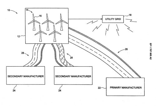
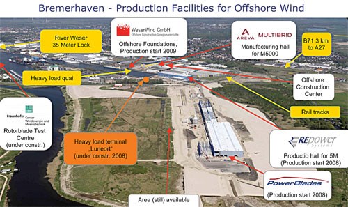
The impetus is intense pressure from utilities and wind farm developers to reduce the cost of wind energy and bring it into competitive parity with fossil fuels. The result is a variety of different strategies that include not only new processing and assembly schemes, but also potential jointed blade designs that will help reduce transportation costs. (Manufacturers also are attacking the high cost of blade transportation with creative construction siting strategies. See the sidebar entitled “Location, location, location,” below).
Increasing capacity without new plants
Blade manufacturing specialist LM Glasfiber (Lunderskov, Denmark) has kept up with demand, so far, by erecting new plants in Goleniów, Poland (production starts at the end of 2008); in Dabaspet, Karnataka, India (opened October 2007); Urumqi, Xinjiang Province, China (opened at the end of 2007); and Little Rock, Ark. (production began in early 2008). But LM’s communications director Steen Broust Nielsen relates that the company’s greater goal is to minimize the need for plant construction by maximizing existing plant production efficiency. “Last year, we added 800 MW of manufacturing capacity, the equivalent of two to three standalone factories, all through increasing throughput,” Nielsen claims. Cost restraint is a key part of this blade manufacturing strategy; however, equal priority is given to refining technology and quality, actually improving LM’s ability to meet its cost goals. Much of what is in place began with LM’s Future Blade technology. Developed while the company designed and built its P 61.5 blade, currently the world’s longest at 61.5m/202 ft, Future Blade was aimed at producing longer, lighter and stiffer blades without using carbon fiber or increasing cost. Many different initiatives were involved, including a holistic view of blade development as a continuous interaction between design, materials and process. A key technology was Rotor Opt, a software tool developed in house that enables LM to analyze and integrate material cost, laminate design, aerodynamic design and structural design. The software helps LM constrain costs by reducing the complexity of its all-glass blade designs and by developing a uniform laminate plan, based on design-for-manufacturing principles, which increases blade quality but reduces kitting and layup costs. Additionally, the heated molds first used with the P 61.5 have been transitioned to unheated molds, saving capital expenditure and energy costs.
Glass vs. carbon, infusion vs. AFP and ATL
Like LM Glasfiber, General Electric (GE, Schenectady, N.Y.) also is interested in cutting wind blade production costs. “Our main objective when looking at composites in GE wind power is to reduce the cost of wind energy to less than fossil fuels,” says GE Global Research (Niskayuna, N.Y.) communications manager Todd Alhart. “Thus, all R&D in this area is processed through that filter.”Unlike LM, GE has a long history of carbon fiber use in a range of applications. At GE Global Research, the company’s centralized R&D division, composites form one of its core technology areas, with applications across its product spectrum. Alhart explains that GE composite propellers and turbine blades in aircraft engines have used carbon fiber for many years and easily achieve more than 100 million fatigue cycles, similar to what wind blades must withstand. He stresses that the question for GE is, Can carbon fiber buy its way onto the turbine? “As we move to larger blades, carbon fiber certainly may do so, but it hasn’t so far,” says GE Global Research composite specialist Scott Finn.
Finn says GE as a whole has looked at automated layup very seriously over the past five years across all of its applications but often found it problematic: “With jet engine blades, the challenge has been complex geometry, while with wind blades the problem is size.” He explains, “In the past, fiber placement and automated tape laying just have not had the advances necessary to overcome these issues. However, now these technologies have progressed to where it might begin to make sense to implement them in our composite products.” Thus, GE Global Research has acquired automated tape laying (ATL) and automated fiber placement (AFP) equipment and has active programs in place to quantify the cost of each process for individual products. Finn details, “We have to know exactly where the numbers fall in order to make that choice of when and where to implement automation.” For wind power, the drawbacks of AFP and ATL are the size of the machines required and corresponding capital expense. However, potential improvements in quality and increased factory throughput are big benefits. Most of this automated equipment has been installed at GE’s new composites manufacturing R&D center outside of Munich, Germany. “We can now build structures greater than 10m [33 ft] in length, which is a great step between core R&D and full-scale manufacturing,” says Finn.
LM Glasfiber’s Nielsen agrees, noting that his company is confident in its ability to make future blades to meet customer demands without carbon fiber, and believes future developments in automation will not make carbon fiber more attractive: “I still have reservations toward carbon fiber because the airline industry is moving toward much more composites-intensive planes, and they’re willing to pay much higher prices.” Beyond the likely high cost of aerospace-grade carbon, he continues, is the question of adequate supply: “I’m not sure carbon fiber production can scale to meet both global aircraft and global wind industry demand.”
“The agreement with DeWind represents another strong vote of con-fidence by a leading-edge wind energy company in the expanded use of carbon fiber,” says Zsolt Rumy, Zoltek’s chairman and CEO, whose company just opened a new production facility in Mexico (see "News" story in this issue) that is expected to end supply problems for its customers. The carbon blades are used in DeWind’s D8 turbine, which it has sold to customers in India, the U.S. and China. Zoltek has a similar agreement in place with Vestas Wind Systems AS (Randers, Denmark) to deliver $300 million of carbon materials for rotor blades. And MTorres (Pamplona-Huesca, Spain) is another blade producer using Zoltek fiber prepreg for its 40m/131 ft blade’s spar.
Blades made in more transportable pieces
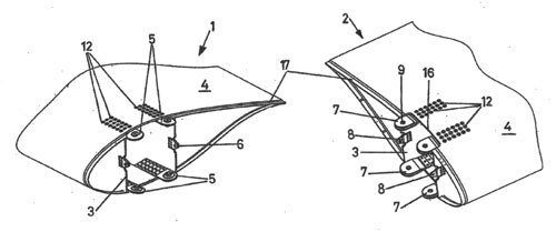
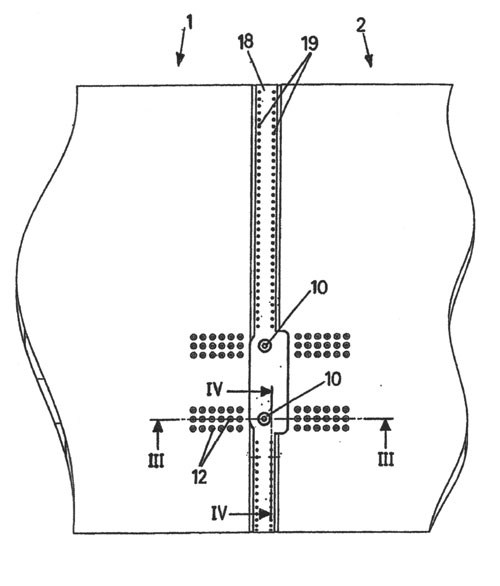
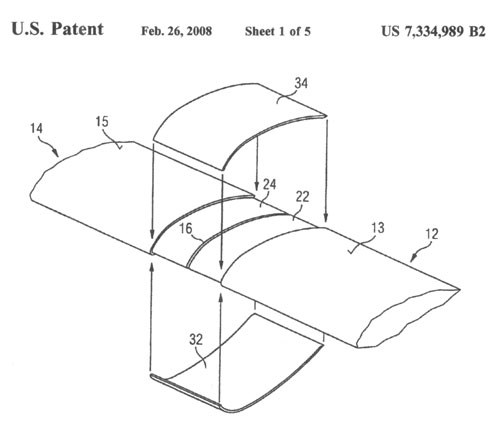
It has been rumored for some time that several manufacturers will soon debut blade designs that permit their manufacture in shorter, more transportable sections that can be assembled at or near the destination wind farm. Although leading manufacturers were mum about their current strategies for doing so, an HPC search turned up a fairly diverse collection of documents that detail a variety of different approaches to jointed blade fabrication and assembly. It is important to note that there is no guarantee that the patented technologies described will be used by the companies involved. For example, GE Global Research composite specialist Scott Finn confirmed that GE is considering a variety of concepts to make multipiece blades, both with bonded connections and designs featuring mechanical attachments: “However, we have not convinced ourselves that it is an attractive solution yet,” he points out. The patents do, however, indicate a broad range of R&D possibilities and certainly imply that there is a fairly large landscape of development efforts currently underway.Patent U.S. 2008/0145231 A1 was filed in March 2005 and awarded June 19, 2008 to Jose Ignacio Llorente Gonzales and Sergio Velez Oria, both of Pamplona, Spain — headquarters for the world’s second largest wind turbine manufacturer, Gamesa. Its claims include a wind blade divided into two or more modules “consisting of outer aerodynamic walls” and “a longitudinal inner reinforcing structure.” The modules are joined via flanges at the ends of the longitudinal reinforcing structure, which have alignable openings for receiving coupling elements. The patent claims to achieve the objective of providing a mechanical fastening system designed for “easy-to-carry-out connections, which facilitates assembly of the blades in the field.”
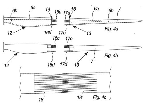
Patent U.S. 2008/0069699 A1 was filed in June 2004 and awarded March 20, 2008 to inventor Anton Bech of Ringkøbing, Denmark — Nacelles business unit headquarters for wind turbine manufacturer Vestas. This patent details a method for bonding two or more wind blade sections by using connection surfaces with dentate ends that are very long and narrow, essentially formed by triangular-shaped protrusions which are easy to manufacture and connect. The dentate connecting surfaces create an adhesively bonded joint with “a much higher tensile strength as the longitudinal forces of the blade is transferred to longer, larger and nonperpendicular connections of the sections.” Thus, the patent claims, it is possible to “re-establish the strength of the wind turbine blade” even when made from multiple bonded segments.
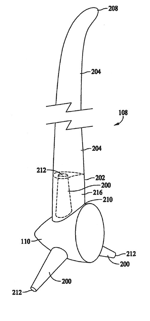
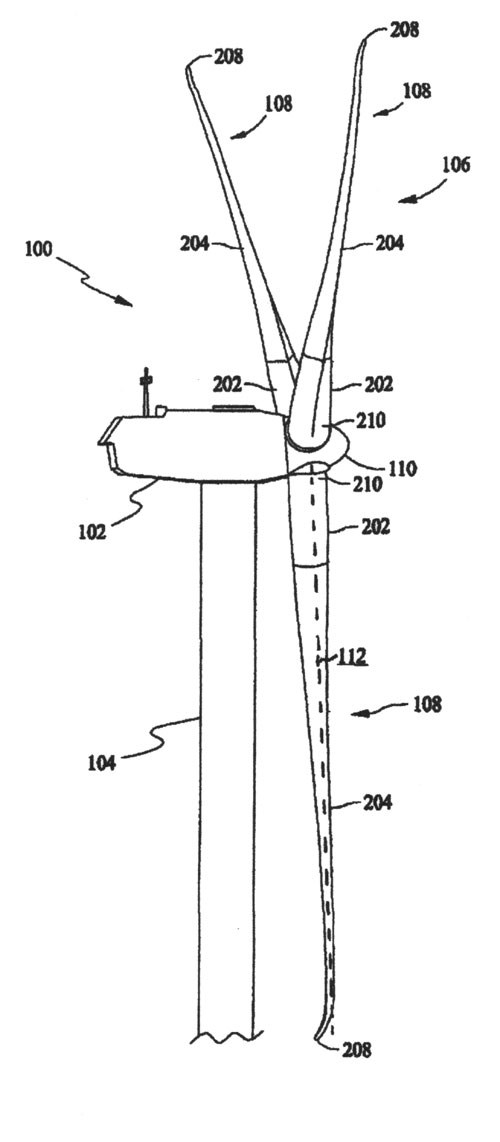
Patent U.S. 7,381,029 B2, filed in September 2004 and published on June 3, 2008, divides the rotor blade into two sections, the first being about 30 percent of the total assembled blade length from the root section and a second section would comprise the remaining 70 percent. The first section comprises of a skirt or fairing that fits over a hub extender, which, in turn, is affixed to the hub and has a pitch bearing at the end opposite its hub mounting. The skirt is mechanically coupled to the outboard section by gluing, bolting, attachment to a frame, or other method. This design enables components to be more easily transported to wind farms and then assembled on site. It also enables changes in blade design during the life of the wind turbine by simply replacing the outboard section.
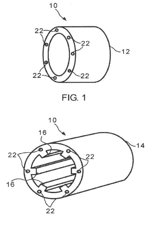
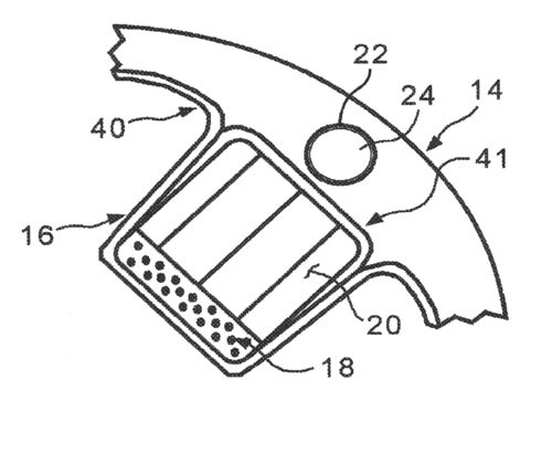
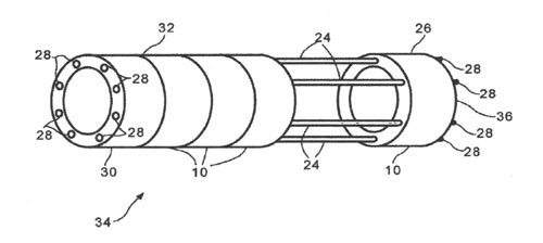
Patent U.S. 7,393,184 B2, filed in November 2004 and awarded to GE on July 1 this year, describes a blade made from multiple stacked segments held together with a number of cables. The modular segments are made with molded-in conduits that enable threading and tensioning cables through multiple segments and then clamping the cables to hold the segments together. Each segment is formed from a monolithic composite shell with internal stiffeners made using unidirectional carbon fiber/epoxy spar caps “to carry blade bending loads in axial tension or compression” and balsa-cored webs “to carry transverse shear due to blade bending.” Cables (which could possibly be made from tensioned braided steel), and stiffeners would be aligned radially to handle axial and shear forces exerted on the blade.
Related Content
NCC reaches milestone in composite cryogenic hydrogen program
The National Composites Centre is testing composite cryogenic storage tank demonstrators with increasing complexity, to support U.K. transition to the hydrogen economy.
Read MoreHonda begins production of 2025 CR-V e:FCEV with Type 4 hydrogen tanks in U.S.
Model includes new technologies produced at Performance Manufacturing Center (PMC) in Marysville, Ohio, which is part of Honda hydrogen business strategy that includes Class 8 trucks.
Read MoreNovel composite technology replaces welded joints in tubular structures
The Tree Composites TC-joint replaces traditional welding in jacket foundations for offshore wind turbine generator applications, advancing the world’s quest for fast, sustainable energy deployment.
Read MoreComposites end markets: Batteries and fuel cells (2024)
As the number of battery and fuel cell electric vehicles (EVs) grows, so do the opportunities for composites in battery enclosures and components for fuel cells.
Read MoreRead Next
Wind turbine blades: Big and getting bigger
Two decades of technical and market development has made this once marginal application a global giant and one of the world’s largest markets for composites.
Read MoreCarbon Fiber in the Wind
Is there a market for carbon composites in wind turbine blade construction? Yes, but the real question is, how big will it be?
Read MoreDeveloping bonded composite repair for ships, offshore units
Bureau Veritas and industry partners issue guidelines and pave the way for certification via StrengthBond Offshore project.
Read More

