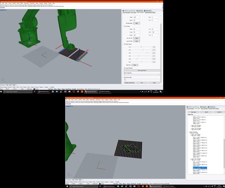
Addcomposites' virtual demo on how to make an AFP composite laminate
Readers are walked through how to program and operate the AFP-XS plug and play system.

Witnessing the entire process of digitized composite layup usually requires you to travel and visit the facility where the AFP/ATL systems are running. This blog post by Addcomposites walks you through a virtual demo video experience, showing how to program and operate the company’s compact, plug and play AFP-XS system for producing composite products or shapes.
Object to Lay
For the very first demo, we are starting with a really basic rectangular shape. The rectangle base laminate is 400 × 450 millimeters in size with a central patch laminate of 100 × 150 millimeters.
- The base laminate has the fiber orientation of [0 degrees / 90 degrees /+45 degrees /-45 degrees]
- The central patch laminate has an orientation of [+45 degrees / -45 degrees].
- The total six-layer laminate has to be laid without any overlaps in the fiber and the maximum gap allowed was 1 millimeter.
Off-Line Programming: ADDpath
The ADDpath software is a plug-in on top of commonly used CAD modeling platform Rhino. The key feature of creating the planning software with this approach provides:
- Accessibility : The ADDpath was built with the goal of accessibility and customization in mind. The open platform allows for different material uses, layup techniques, fiber paths, and mold shapes to be used.
- Fast setup: ADDpath requires minimal installation time, and since most universities/R&D centers/technical clusters have existing Rhino subscriptions, there is no additional learning curve or infrastructure investments.
- Freedom: The Rhino ecosystem allows for visual programming elements, that can be implemented on top of the ADDpath generated programs.
Process
The programming process is quite intuitive in its nature, and following these simple steps will ensure success.
- Import the CAD file in .stp format to ADDpath.
- Start with adding the lay-up sequence [0 degrees / 90 degrees / +45 degrees / -45 degrees] for the base layer
- Check for the Layup and Speed parameters
- Click on "Add Layup" and select the base surface. Now you can see Layup 1 appears in the layup window.
- Enter the layup sequence for the central patch laminate [+45 degrees / -45 degrees].
- Click on “Add Layup” and select the central patch surface. Now you can see Layup 2 appears in the layup window.
- To finalize the layup, click on “Plan Layup.” This brings up the material needed for the layup and the time estimate to do the layup.
- Now we can visualize the planned layup, through the layup tree. Here you have option to suppress individual passes, visualize individual layers, and more.
- Now we move onto the Simulation stage, where we see the robot (requiring only an initial upload, then is available each time thereafter) appears and simulates the layup of each pass. Presently the robot will turn pink if it is hitting any soft limits, and red if it hits a hardware limit. The upcoming version will have collision detection between the AFP-XS and mold as well.
- During the Visualization you can slide through the frames of robot motion to ensure smooth operation in virtual environment. This helps in optimizing the operations and accident avoidance during actual operation. Alternatively, you can hit “Play” to see a full animation of your layup.
- Once satisfied with your simulation and layup, click “Generate Robot Program.” This will create code in the specified robotic language. This is currently available for KUKA, for which you can use the OrangeEdit application to visualize the generated program. Save the generated program to your USB drive, and then transfer it to the KUKA control box.
To read the whole blog with videos go to: https://www.addcomposites.com/post/virtual-demo-how-to-make-flat-laminate-using-afp-xs
Related Content
Plant tour: Teijin Carbon America Inc., Greenwood, S.C., U.S.
In 2018, Teijin broke ground on a facility that is reportedly the largest capacity carbon fiber line currently in existence. The line has been fully functional for nearly two years and has plenty of room for expansion.
Read MorePEEK vs. PEKK vs. PAEK and continuous compression molding
Suppliers of thermoplastics and carbon fiber chime in regarding PEEK vs. PEKK, and now PAEK, as well as in-situ consolidation — the supply chain for thermoplastic tape composites continues to evolve.
Read MoreCarbon fiber, bionic design achieve peak performance in race-ready production vehicle
Porsche worked with Action Composites to design and manufacture an innovative carbon fiber safety cage option to lightweight one of its series race vehicles, built in a one-shot compression molding process.
Read MoreJeep all-composite roof receivers achieve steel performance at low mass
Ultrashort carbon fiber/PPA replaces steel on rooftop brackets to hold Jeep soft tops, hardtops.
Read MoreRead Next
“Structured air” TPS safeguards composite structures
Powered by an 85% air/15% pure polyimide aerogel, Blueshift’s novel material system protects structures during transient thermal events from -200°C to beyond 2400°C for rockets, battery boxes and more.
Read MoreDeveloping bonded composite repair for ships, offshore units
Bureau Veritas and industry partners issue guidelines and pave the way for certification via StrengthBond Offshore project.
Read MorePlant tour: Daher Shap’in TechCenter and composites production plant, Saint-Aignan-de-Grandlieu, France
Co-located R&D and production advance OOA thermosets, thermoplastics, welding, recycling and digital technologies for faster processing and certification of lighter, more sustainable composites.
Read More


