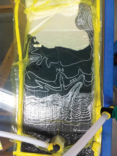
Aiming infusion at the application
With so many process variables to play with, how do you know which new solutions that promise better, faster infusion are right for your application?
Much has been written about resin infusion processing. Early on, infusion was a boon to open molders, especially those who made boat hulls, wind turbine blades and other large parts. It reduced resin use and increased fiber volume fraction and strength/stiffness-to-weight. And it limited worker exposure to HAPs and VOCs at a time when governments were looking askance at “bucket-and-brush” operations. It was better, but not much faster.
As boatbuilders and blademakers pushed toward lighter-weight composites with higher mechanicals, and as aerospace companies sought to reduce costs with out-of-autoclave processes yet maintain prepreg performance, innovators saw a need for greater speed. Soon, ovens accelerated cure, and then resin flow became the focus. Hot items on that front included grooved core and a variety of flow media. Heat, it was said, could reduce resin viscosity and thereby increase flow. And a year ago, the rush was on toward very low-viscosity or snap-cure resins.
Since then, however, the infusion conversation has shifted. A chorus of voices has raised questions, suggesting there is a point at which fast becomes too fast. Although there is no consensus on how best to infuse, a growing group agrees that process control is more important than speed.
Permeability and reinforcements
Every reinforcement supplier has a product “tailored” for infusion and promises improved speed, wetout or mechanical properties. But what makes a fabric suitable for infusion? Is faster flow always better?
The measure of how easily a resin flows through a material is called permeability. Fabrics with high permeability infuse more quickly. After 13 years as head of technical development for Vectorply Corporation (Phenix City, Ala.), Philip Steggall founded composite design and development services company Bravolab (Jamestown, R.I.). He routinely tests materials against their suppliers’ claims. His findings? “Wovens typically don’t infuse as well as stitched materials, leaving dry spots within the tows and air bubbles where the fibers intersect,” he reports. “Double-bias (± 45˚) does not infuse well because the stitching process flattens everything out, causing the tows to nest. Unidirectionals made with heat-set cross yarns [hot-melt] look great but are the hardest to infuse because the resin cannot penetrate through the ply stack. Alternatively, stitched unis allow resin to drop down through the needle holes and are easier to infuse.”
Does that mean more space in a fabric is better? Not necessarily, says resin infusion consultant André Cocquyt (ACSM Inc., Harpswell, Maine; see Editor's note at end of article). “To make fabrics more permeable, you must create void space that does not collapse/compress under vacuum.” He cautions, however, “a lot of the fabrics out there have resin channels that are detrimental to the mechanical properties.” If the fiber form has too much void volume in the channels between the tows (intertow flow), shrinkage of the resin between the tows can create stresses on the microlevel. Further, if resin flows too freely between the tows, the result could be incomplete wetout within the tow (intratow flow). As a result, says Cocquyt, “many infusion-friendly laminates do less well in fatigue.”
“The permeability of fabrics for infusion is a balancing act,” notes Stephen Misencik, technical marketing manager for stitched multiaxial supplier SAERTEX USA LLC (Huntersville, N.C.). “From the process point of view, you want to achieve the flow rates you need for the project, but high permeability rates aren’t necessarily what you want for the mechanical properties needed.” On a large infused fiberglass barge cover that measures roughly 20 ft by 30 ft (6m by 9m) and weighs 2,500 lb/1,134 kg, he notes, “We used a different size of input fiber to open the fabric slightly, increasing the space between the glass tows from 0.2 to 0.4 mm [0.0079 to 0.057 inch],” he explains. “This slight opening was enough to really enhance flow and achieved the production speed and wet out we needed.” Most important, it did not compromise the key mechanical properties of compressive or bending strength and stiffness.
Glass vs. carbon
Permeability issues also vary based on fiber type. “The space between the 5- to 7-micron diameter filaments of carbon fiber is almost nonexistent compared to that between the 20-micron diameter glass fiber filaments, especially when compacted under a vacuum,” Steggall illustrates. “Glass is easier to infuse because of the bigger diameter bundles.” He also notes that carbon fabrics use stitch yarns that are half the size of those used in most glass fabrics, so the vertical openings are much smaller. “There is no such thing as a fast infusion of carbon fiber,” Steggall contends. “It is very difficult to achieve the same speed of flow through the depth as across the area.”
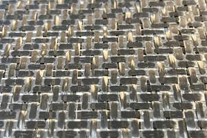
Steggall’s own search for a way to speed vertical flow led to a mesh made from randomly oriented continuous nylon 6 monofilament. “At a very small amount of weight — 6 g/m2 (0.02 oz/yd2) or about the weight of two paper clips,” he reports, “the mesh induces flow in almost any type of carbon fabric.” The flow improves regardless of fiber angles (e.g., 0°/90°, ±60°, etc.). When the mesh is attached to each ply of a 300 g/m2 (8.8 oz/yd2) stitched carbon fabric, it creates a channeling effect like that from a 0° oriented uni fabric and the stitching. For heavier 400 g/m2 (12 oz/yd2) fabrics, he uses a 12 g/m2 (0.4 oz/yd2) mesh. “For me, this is the way to achieve permeability in carbon fabric because it provides good strength and toughness properties with only marginally more resin in the laminate.”
The material is now used by Gunboat International (Wanchese, N.C.) in its 55-ft/17m all-carbon-fiber production sailing catamaran. The company infuses the complex hull in one piece, with the nylon mesh layered between each ply of woven and stitched multiaxial carbon fiber fabric. Most impressive, it aids flow in the chine (transition from the hull bottom to the hull side), where 83 plies of carbon fiber unidirectional fabric and 10 plies of carbon fiber biaxial fabric provide resistance to deflection along the inner side of each hull. Steggall says the nylon web provided what the project needed: “consistency in the infusion and wet out at low risk plus 18 percent more energy absorption in impact testing.”
Trade-offs to achieve flow
Although permeability limits can be overcome by using flow media or low-viscosity resins (as little as 10 cps), it’s important to do so only when the potential issues and trade-offs are well understood. “The problem with resins that have low viscosity (10 cps) at room temperature is that they typically have very low elongation and are very brittle,” Steggall warns, adding that they form thin films as they are separated by the reinforcements in the laminates. They also tend to reduce thickness. “I have gone from a 220 cps resin down to a 180 cps resin and lost 10 percent of the stiffness in the same laminate.”
Cocquyt, however, offers a caveat: “Vinyl ester and unsaturated polyester resins do become brittle when you add large percentages of styrene.” He says that adding diluents to epoxies does not lower elongation at break very much, but it does reduce their heat deflection temperature.
Surface flow media (distribution media) are easy to use and effective, but they add a processing step because they must be removed when the part is done. They also absorb resin, which becomes waste. Boatbuilding veteran Jay Carpenter, now a resin infusion instructor at Abaris Training Resources Inc. (Reno, Nev.), often uses them to solve permeability problems. He counsels, “When using a surface flow mechanism, there is a fine balance between moving the resin along the required distance and moving it too fast so that you end up with dry spots.” To prevent resin from hitting the vacuum line before it wets out the dry stack, he wraps the line with a peel ply or other ultralow permeability material and then stops the surface medium several inches away from the vacuum line. “For me, slow flow works better,” Carpenter claims. “Typically, gel time of the resin is not my enemy. I can get infusion epoxy resins formulated with a gel time anywhere from 30 minutes to 30 hours.”
Steggall believes that a speed of 0.75 inch/min to 1 inch/min is a good target for infusing a solid carbon fiber laminate using vinyl ester or epoxy resin in the 200 cps viscosity range. “Achieving a high fiber fraction — like 68 percent by weight — is risky at very fast speeds. You can have dry spots in the laminate at those speeds, or miss a tow bundle. However, if you slow down to 0.25 inch/min. then you’re susceptible to stall out.”
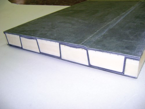
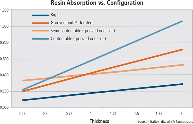
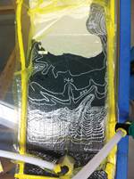
Flow media “cores” and grooved foam or balsa cores that promote flow inside the laminate are also effective, but they also absorb resin and, because they can’t be removed, increase part weight. Steggall understands the appeal of grooved core. “With those huge grooves, you can get just about anything to infuse,” he quips, but he adds that in tests where core with grooves on both sides was infused between sheets of plate glass, the core’s weight was increased significantly. He estimates that even knife-cut core (thinner grooves) increases in weight by 10 to 15 percent (see also Fig. 1).
Steggall says the weight increase might be justified depending on what factors drive a project. “You must ask what properties are you looking for? There are so many tricks you can use, but what do they really buy for what they cost in time and money?” Steggall enters into a spreadsheet the price per square foot of everything he’s going to use to evaluate what each component really offers vs. its cost.
And perhaps time saved is worth the extra cost. Carpenter teaches his students to model and test: “You need to do flow modeling, which can be as simple as laying out different colors of tape for resin feed lines and vacuum lines or using one of the different software programs available. To remove any doubts, nothing beats running an actual test, which does not necessarily have to be in the mold.” Carpenter stresses that what’s important is to include everything that will be in the laminate stack, infuse it and see what happens. Try different materials, play with different process variables, measure flow times and then test for mechanical properties.
Tacking the dry stack
Dry spots and racetracks are typically caused when resin flow must wrap around something, such as cutouts and the edges of core in a sandwich laminate. Steggall advises that when dry laminate layers are tacked together or a dry stack is adhered to vertical surfaces, using the least possible amount of spray adhesive will give the laminate the best chance to sit tight on a core and in the corners and reduce the risk of flow issues. “When you spray tack adhesive to the point that the whole thing is thoroughly tacked together, it wants to bridge,” Steggall says. He prefers to lay in the fabric as loose as possible with only spot tacking where absolutely necessary.
Carpenter agrees, and adds, “We advise to use products that are chemically formulated to emulsify in a way that doesn’t degrade laminate properties. This isn’t possible with spray adhesives that are basically rubber or thermoplastic digested in solvent.”
Another option is to use fabrics that have been precoated with adhesive. SAERTEX, for example, designed its patented SAERfix fabrics to mitigate fiber movement when an RTM mold is closed. Yet Misencik points out that adhesive is used sparingly. “We never use more than 2 percent of the fabric’s areal weight.” Thus, the material is not “boardy” and can be removed and repositioned. This helps when laminates are tacked to complex shapes and geometries, and it helps maintain fiber alignment in thick laminates (30 to 50 mm/1.2 to 2.0 inches) while a vacuum bag is applied.
“With SAERfix, the fibers do not move,” Misencik claims, “even with laminates up to 120 mm [4.7 inches] thick.” Similarly, it helps with fixation of core materials and inserts. Available in both polyester (UP) and epoxy (EP) compatible formats, the adhesive has been designed to become part of the laminate. Misencik details, “The EP adhesive is bisphenol A-based, so it actually crosslinks and becomes part of the matrix, while the UP adhesive is a styrene-soluble ethylene vinyl acetate (EVA, a common adhesive) which remains in the resin, much like a filler.” The benefit to the laminate is not insignificant: Misencik says the EVA, for example, reduces interlaminar shear (ILS) properties by a mere 3 to 5 percent (vs. a baseline without adhesive) but using an aerosol spray adhesive can drop ILS by as much as 15 percent.
SAERTEX test results show that the materials do not slow resin flow, obstruct wetout or degrade mechanical properties. Misencik adds that the material “improves the quality of the final infused part by enabling homogeneity in the amount of tack adhesive applied. There is no excess and no missed areas.”
Single- vs. double-bagging
The ultimate goal of infusion is a thoroughly wet out, well-compacted laminate without air bubbles or dry spots. Although that is something proponents of double-bag infusion claim to have achieved (see “Learn More”), others suggest the same result can be had with conventional single-bagging.
After receiving many questions about double-bagged infusion, Composites Consulting Group (CCG) recently conducted side-by-side testing. Launched in 2010 by core materials manufacturer Diab International AB (Laholm, Sweden), CCG offers computer analysis, testing and infusion process development and flow-modeling expertise. CCG process specialist Dean Callander says, “We wanted to see for ourselves if it actually produces improvements that merit the additional cost, complexity and potential risk.”
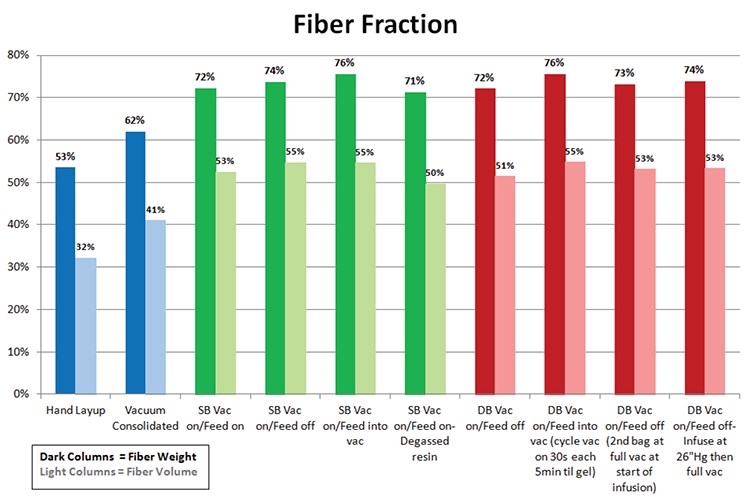
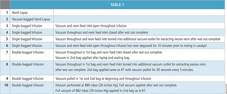
The first round of tests involved 10 samples. Each measured 0.5 ft by 2 ft (152 mm by 610 mm) and was made using six plies of a nominal 36 oz/yd2 (1,221g/m2) 0°/90° biaxial stitched E-glass fabric from Vectorply and CoRezyn vinyl ester resin from Interplastic Corp. (St. Paul, Minn.). Two panels were made using traditional hand layup open molding for a baseline; one was vacuum-bagged during cure. Half of the remaining eight panels were infused under a single vacuum bag, and half were infused using a double-bag process. All materials and consumables were identical. All laminate stacks were held under vacuum for one hour before infusion (see “Flow-front dynamics: Heat and vacuum hold” at the end of this article or click on its title under "Editor's Picks," at top right), and all panels remained under vacuum during infusion and cure, using the same vacuum manifold. But to test specific infusion processing theories, each of the eight samples were processed uniquely, as noted in Table 1. After cure, each sample’s laminate thickness was measured at 2 inches (51 mm) from each end and in 1-inch/25.4 mm increments, and the panels were weighed. Void and fiber fractions were determined using test methods ASTM D2584 and ASTM D2734. Separate samples from the same panels were sent to the National Institute for Aviation Research (NIAR, Wichita, Kan.) to verify the results. Fig. 2 shows the results. “We did not see any real improvement in the laminate by using double-bagging,” summarizes Callander. The weights of the single- vs. double-bagged infused panels were all within 0.6 kg/m2 (0.12 lb/ft2), and the thickness varied less than 0.3 mm (0.01 inch).
CCG performed a second round of testing. The infusion was repeated for the combinations of process variables that produced the best results in its first round (panels 3, 4, 6, 7 and 10 from Table 1). The panel weight remained within 0.2 kg/m2 (0.04 lb/ft2), and the thickness varied by only 0.14 mm (0.006 inch).
“From what has been written about the process, people are expecting a lot of extra pressure to be exerted on the laminate due to a second vacuum bag, but the physics just isn’t there,” Callander concludes. “My only explanation of why it seems the double-bag exerts more pressure is that the action of the two bags together seems to smooth out the wrinkles in the first bag so the whole set up is tighter.” He says that a second bag can help achieve full vacuum integrity in the setup, overcoming or mitigating issues in getting the first bag to seal and maintain vacuum, but he notes that “with proper bagging technique, that shouldn’t be needed.”
Callander posits that the technique of applying a vacuum through the feed line to draw extra resin from the laminate is possible with a single bag, but it introduces unnecessary risk: “We did not have good results with this technique — all of the laminates were very dry with voids.” Callander believes people are looking to double-bagging and pulling out excess resin to achieve a higher fiber fraction, but he insists that outcome is readily achievable with sufficient process control. “CCG uses single-bagging exclusively,” he reports, “and 70 percent fiber fraction by weight is common.”
Cocquyt’s review is mixed: “Though the number of samples was too small — only one test per configuration — this testing has shown that double-bagging produces a minimal difference in final outcome.” He believes a larger test matrix would be beneficial and is discussing how an industry partnership might pursue this. But he agrees that the reduced weight, higher fiber fraction and better consistency credited to double-bagging are more likely due to greater attention to detail and the use of superior equipment.
Reward vs. risk
The overarching conclusion from CCG’s testing is that the process must match project requirements. Callander notes that double-bagging was developed in the aerospace industry, where a 1 percent reduction in void content and elimination of a 0.3-mm/0.012 inch variation in thickness might be worth the thousands of dollars in development and consumables if it eliminates an autoclave. But that typically is not the case in boats, even in racing yachts, using infused carbon fiber.
Steggall agrees. “I think we should be driving infusion toward a low-risk process,” he says. “Pushing higher mechanical properties via low resin content ... presents too many ways to jeopardize the part.”
Cocquyt stresses process control. “Infusion physics is straightforward, which is why resin infusion became a mainstream technology in a short time span. But it does require exactness and standard operating procedures, with no tolerance for ‘fudge’ factors.”
At day’s end, an extra bag, a resin heater or a snap-cure resin alone isn’t the answer. Thorough testing is. Carpenter sums up: “You can create repeatability in any infusion process, but you have to manage the process, not let it manage you.”
COMPOSITESguru.com
Molding Products LLC
Editor's note: Andre Cocquyt is a coinventor of Temperature Controlled Molding (TCM), a heat-activated cure and infusion control technology for thick laminates, marketed by TCM Composites (Augusta, Maine). Read more about TCM in “The evolution of infusion” and/or “New infusion regime for superthick laminates” by cliking on their titles under "Editor's Picks," at top right.
Related Content
XlynX Materials BondLynx and PlastiLynx for low surface energy PP, PE substrates
Award-winning Xlynx materials use breakthrough “diazirine” technology to boost bond strength up to 950% as adhesives, primers and textile strengtheners.
Read MorePontacol thermoplastic adhesive films are well-suited for composite preforms
Copolyester- and copolyamide-based adhesive films eliminate the need for sewing threads or binders when stacking laminates while improving the final part’s mechanical properties.
Read MoreResins, additives, adhesives and 3D printing solutions
CAMX 2023: Arkema’s broad portfolio of products for composites fabricators aim to enhance performance, durability and sustainability.
Read MoreHenkel receives Airbus qualification for European aerospace manufacturing facility
The adhesive company’s Montornès, Spain, plant has been approved as a standard and raw materials supplier for various Airbus platforms, adding to its work in lightweighting, fuel efficiency and automation.
Read MoreRead Next
Flow-front dynamics: Heat and vacuum hold
Three infusion experts talk about ways and means to avoid erratic flow fronts during resin infusion processes.
Read MoreAll-recycled, needle-punched nonwoven CFRP slashes carbon footprint of Formula 2 seat
Dallara and Tenowo collaborate to produce a race-ready Formula 2 seat using recycled carbon fiber, reducing CO2 emissions by 97.5% compared to virgin materials.
Read MoreDeveloping bonded composite repair for ships, offshore units
Bureau Veritas and industry partners issue guidelines and pave the way for certification via StrengthBond Offshore project.
Read More

