CAMISMA’s car seat back: Hybrid composite for high volume
Recycled fibers, in-situ polymerized PA12 and steel inserts combined in one-shot process to cut weight 40 percent at competitive cost, cycle time and safety.
Carbon fiber-reinforced plastic (CFRP) is an attractive solution for automotive lightweighting, but the material and manufacturing costs can exceed 10 times that of steel. The Carbon fiber/Amid (short for polyamide)/Metal Interior Structure using Multi-material System Approach (CAMISMA) collaborative aims to change that equation. Funded by the German Federal Ministry of Education and Research (BMBF, Bonn and Berlin), CAMISMA’s goals include:
- Reuse of byproducts from carbon fiber production and/or recycled fibers to help limit incremental component cost (i.e., cost due to new materials and manufacturing) to <$5/kg (≈$2/lb) and help reduce CO2 emissions for CFRP structures.
- Enable low-cost, short-cycle manufacturing by combining thermoforming with injection overmolding and attachment of metal inserts in a one-shot process.
- Develop an automobile seat design that reduces weight 40 percent vs. conventional metallic constructions.
- Meet front and rear impact safetyrequirements.
Johnson Controls Inc. (JCI, Burscheid, Germany) supplies integrated automotive seating modules to OEMs and has led CAMISMA’s simulation and design efforts with team members noted below. The CAMISMA team began work in 2011 and is scheduled to conclude manufacture and crash testing of a full-scale seat back structure in early 2015.
Building on past success
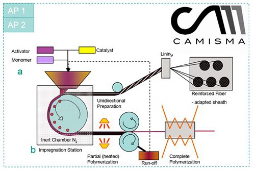
CAMISMA takes advantage of three recently developed technologies. The first is a new type of unidirectional (UD) polyamide (PA) prepreg tape, developed by Evonik Industries AG (Marl, Germany) and Toho Tenax Europe GmbH (Heinsberg, Germany). Dr. Eleonore Moeller, project manager at Evonik’s Science-to-Business division, Creavis, acknowledges that continuous-fiber PA6 and PA12 tapes are already available, but points out that they are expensive because highly-viscous PA polymers require melting and solvent-reduction before they will thoroughly impregnate carbon fiber. To make the new tapes, continuous carbon fiber is saturated with a monomer, laurolactam (a low-viscosity constituent of PA), rather than a polyamide polymer. Prior to wetout, the monomer is mixed with catalyst and an anionic initiator/activator, which enable polymerization into PA in situ, that is, during the tapemaking process. “We polymerize that matrix into PA12 around the fibers,” Moeller explains, claiming, “The low-viscosity monomer achieves impregnation very quickly, but with a high quality that improves fiber-to-resin adhesion.” The monomer is not only less expensive than an already processed PA but its use also eliminates steps and solvents from processing. Fast wet out and polymerizing after impregnation also boost the PA12’s mechanical properties, Moeller adds, noting that the latter does so “because it builds higher molecular weight.”
For CAMISMA, Evonik used Tenax-E HTS45 12K fiber, with a sizing tailored for thermoplastic matrices. The fibers were supplied to a pilot plant installed by Evonik at, and operated by, the Institute for Textile Technology (ITA, RWTH Aachen University, Aachen Germany). Tapemaking begins with heat treatment of incoming fiber to remove residual moisture prior to impregnation. Fibers are then wet out with the monomer mix, heated and compacted, after which the PA12 tape is ready for molding.
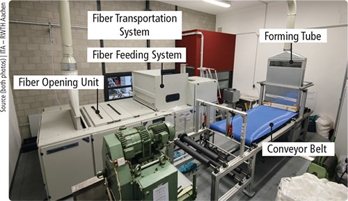
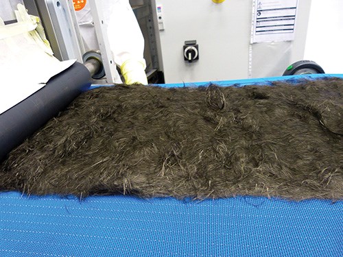
The second technology helped CAMISMA meet its material cost-reduction goal. PA12-powder-impregnated nonwoven mats were made for this project from recycled carbon fiber by Materials Innovation Technologies Reengineered Carbon Fiber (MIT-RCF, Lake City, S.C.). These mats can be impregnated with monomer and in-situ polymerized like the UD tapes to form PA12 organosheets that are thermoformed during the CAMISMA process. Notably, ITA is also working on an alternative: Forming such mats from nascent fibers not collected by rollers during the spinning of polyacrylonitrile (PAN) precursor fibers for carbon fiber production. Supplied to ITA, these PAN fiber segments, which would otherwise be waste, are cut into 2-inch/50.1-mm lengths, carbonized and formed into homogeneous mats, using ITA’s newly developed continuous air-lay process, which prevents the fiber damage and breakage usually associated with mechanical processes (carding and roller carding).
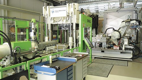
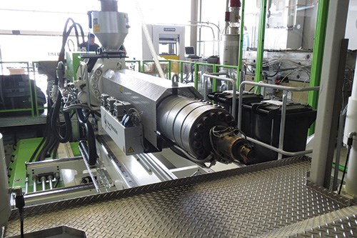
The third technology, a hybrid injection molding/thermoforming process developed during the BMBF-funded SpriForm project, enabled forming of the PA12 tapes and mats, overmolding of plastic features and incorporation of metal inserts in one step. SpriForm’s Germany-based working group was headed by Jacob Plastics GmbH — now HBW-Gubesch Thermoforming GmbH (Wilhelmsdorf) — and included automaker Audi AG (Ingolstadt), organosheet supplier Bond‐Laminates (Brilon), thermoplastics formulator Lanxess (Cologne), injection molding equipment source KraussMaffei (Munich) and the Institute for Composite Materials (IVW, Kaiserslautern). The SpriForm process unites injection molding and thermoforming in a fully automated production cell in which continuous-fiber-reinforced organosheets are preheated by an infrared oven and robotically placed in an injection mold, fixed in place by hydraulic needles, thermoformed and then back-injected with a short-fiber-reinforced thermoplastic that fills the mold cavity to fully overmold edges, ribs and other functional elements. To facilitate overmolding, the KraussMaffei injection system features a compounder that enables customization of fiber length and content.
A key to SpriForm development was understanding the strain-rate-dependent material properties of both short-fiber-reinforced and continuous-fiber-reinforced plastics so that process tooling and parameters could be optimized both for the hybrid materials and hybrid molding. In 2012, Compounding World magazine reported that SpriForm partners believed the process capable of producing parts with high strength and energy absorption at reduced weight vs. metal equivalents and at a lower cost vs. metal hybrids (e.g., steel-aluminum). Audi estimated a SpriForm bumper beam could reduce part weight by 20 percent vs. aluminum designs.
Designing a multimaterial seat
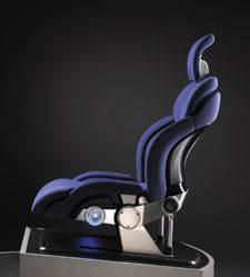
Armed with materials and a process, CAMISMA focused on an optimized design. “The basic task was to develop a lightweight seat back with additional functions integrated into it,” says Axel Koever, manager of new technology at JCI Automotive Seating. “We had already demonstrated rear seat concepts, so we chose a front seat, which has higher loads and where carbon fiber has opportunity,” he recounts. “We then identified a reference seat in production so that we could compare our results to a meaningful benchmark.”
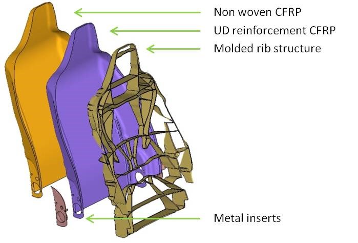
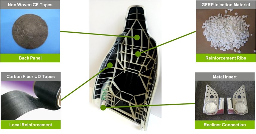
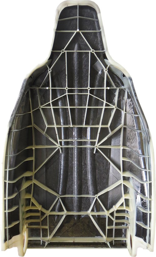
Working with the Institute of Automotive Engineering (IKA, RWTH Aachen University) and JCI’s Structural Simulations Dept., Koever’s team completed dimensioning and design, using HyperWorks from Altair Engineering (Troy, Mich.) and LSDyna from Livermore Software Technology Corp. (LSTC, Livermore, Calif.). “We used the three different materials in a smart way,” Koever explains, “chosen not only because they offered different mechanical and lightweight properties but also different costs.” Because optimized cost was a key goal, the design had to minimize expensive, high-strength material. That was accomplished with the “injection molding material — which is the lightest and also most cost-effective — to support the other materials,” he notes. The nonwoven mat provided a common surface on which the design team, based on the results of its topology optimization, placed and oriented the least amount of material that would meet specified loads. “In the end,” Koever recounts, “we achieved an integrated structure with different wall thicknesses and different mechanical properties where desired, tailored to meet precise loads.”
The computer models were validated by significant materials testing (tensile, compression, flexure, etc.). In the beginning, the in-situ-polymerized UD tapes and nonwoven mats were not yet fully developed, so the design team used comparable UD tapes impregnated with PA by conventional means, and nonwoven mats that were commercially available. “We compared these test properties with our simulations to verify the models,” Koever relates, “and then simplified the HyperWorks output slightly to optimize manufacturability and reduce cycle time.”
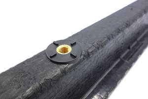
Metal content was a design necessity in the reclining mechanism, which also functions to connect the seat back to the rest of the seat. “But because it is the heaviest material, we wanted it minimized,” says Koever. Crash impact requirements, however, required that load transfer between the metal and composite be optimal. The key innovation here was a special coating for the metal inserts, also from Evonik. Numerous lap shear tests were performed, where metal plates overmolded with plastic were pulled and load transfer between the two measured. They also tested for climatic and temperature effects on this connection, cycling from -30°C/-22°F to 80°C/176°F.
Koever concludes, “We wanted to make sure that combining the different materials would not produce any long-term weakening.” The team’s efforts in that regard were positive: The coating ensured good metal-to-composite bonding, and the overmolding step achieved mechanical locking of the metal inserts. “Now we had a connection strong enough to handle the loads transferred between the seat back and bottom during a crash.”
One-step thermoforming/injection molding
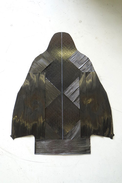
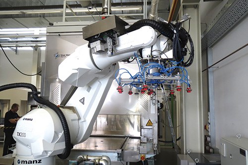
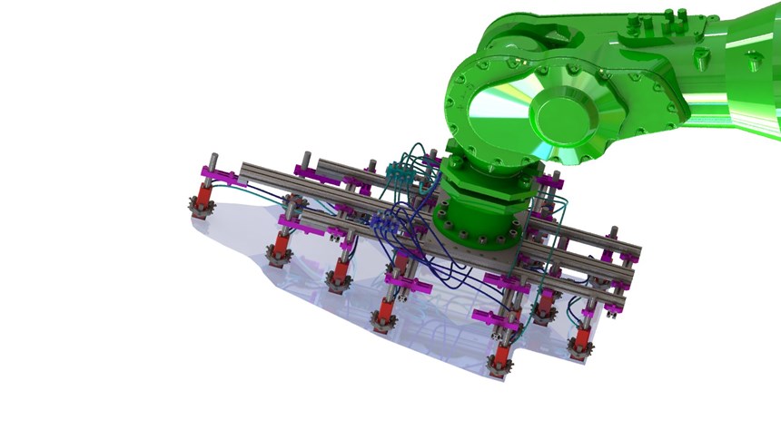
For the CAMISMA project, the SpriForm process began by integrating the PA12-impregnated nonwoven mats and UD tapes into preforms. “We placed the mats and tapes in the right direction in the right place and built the layers of the preform with the nonwoven typically across the bottom of the layup,” reports HBW-Gubesch R&D director, Dr. Marcus Schuck. An ultrasonic welder melted the PA matrix and adhered the layers together (see Step 3). Then, the preform was transferred by a robot with needle grippers into a convection oven where it was heated to between 260°C/500°F and 280°C/536°F. After sufficient heating, a robot moved the preform from the oven to the SpriForm tool, where elements inside helped to locate and hold it in place. Metal inlays for the recliner mechanism had already been robotically placed in the tool and positioned by built-in elements.
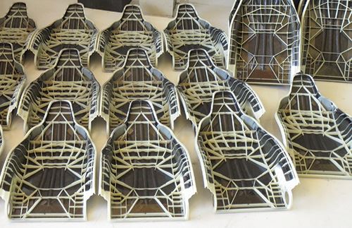
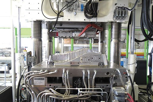
As the mold closed, the preform was pulled and draped over the tool die (pictured in Step 5) and subjected to heat sufficient to ensure good formability as the part assumed its final shape. In the overmolding stage, Evonik’s Vestamid L-GF grade of 30 percent glass fiber-reinforced PA12 compound was injection molded into the closed tool, filling the cavity to form the seat back’s reinforcing ribs as well as functional features like the air bag attachment and trim channel. It also encapsulated the edges and metal inserts. The mold then cooled and ejected the part, with a total molding cycle approaching 90 seconds.
When asked what CAMISMA had to do to adapt or enhance the SpriForm process for its purposes, Schuck responds, “The process was the same, but the materials were new. Our biggest issue was material handling and draping. The heating, picking up and moving of the materials had to be developed for these new materials.” Handling time, in fact, had to be minimized because material temperature was the key to achieving good bond strength between components in the integrated structure. Thus, the preform could not be allowed to cool between the preheat oven and heated SpriForm tool.
The result? According to JCI’s Koever, “The first time we put the SpriForm tool on the injection machine and pulled parts, they looked very good and well-designed.” Weight savings vs. the steel benchmark actually exceeded the 40 percent goal for the structure plus mechanism. For the structure alone, weight was reduced by more than 50 percent. The CAMISMA team began crash-testing full-size seat backs, using test dummies, in September. The first completed test simulated rear-end impact by a car traveling at 30 kmh/19 mph. Koever says there were no failures that presented serious issues and deformation was in line with expectations. “We are comparing the results now to our simulations,” he notes, “but overall, the demonstrator took the loads well.”
Hard questions, real-world answers
But is the process viable for real-world auto production? Koever says yes. Currently, the process is configured for two robots. One takes a finished part out of the tool and places new metal inserts into the tool while the other takes a preheated preform out of the oven and places it into the tool. Schuck states that synchronizing the various transfer and placement operations basically simulates an inline process. Although automated preforming wasn’t available for the project, Koever points out that the equipment for it exists, developed by Fiberforge (Glenwood Springs, Colo., see “Tailored carbon fiber blanks set to move into steel stamping arena,” under "Editor's Picks," at top right) and subsequently acquired by Dieffenbacher (Eppingen, Germany). “We have investigated this with Dieffenbacher to see if target cycle times could be achieved,” says Koever. “Their proposals are very close, which balances with our forming/molding equipment. So the equipment to make this process feasible for mass production is already available, and just a matter of combining the technologies in one place.”
What about auto OEM cost targets? Koever claims the seat back “is reaching the goal of not more than $5 additional cost per saved kg of vehicle weight, which is considered the lightweight indicator in the auto industry. “We think we can stay below this,” he explains, “because we minimized the expense of material. For example, lower-cost injection molding material makes up half of the seat back mass. After 90 seconds, you have a completed part with no secondary operations and the materials are also produced in a continuous way. So this is much more viable to an OEM vs. RTM where one part takes 5 to 15 minutes, making high volume difficult.” Koever adds that although some automakers are using very specialized machines in their development of composites, CAMISMA is using standard injection molding equipment in its process, and although they have used a vertical machine, which has advantages, this is not a requirement for successful processing.
What about performance? Planned lifecycle analysis is still in process, but Koever anticipates that the team will have data that compares the full-scale demonstrator seat back to standard metal seats as well as a full analysis and complete results by early 2015.
When asked about the future of using recycled carbon fiber (RCF) and how that compares to virgin fiber, Koever replies, “For CAMISMA, the recycled material, as far as short fibers, is the same, and the issue with waste in composites production is one that must be solved.” He notes there are viable industrial-scale RCF suppliers, but observes, “You can also use glass fabric organosheet, so there are a lot of possibilities. However, this CF nonwoven has benefits if you consider surface quality and planarity [flatness]. It also aids in impact performance. With CAMISMA, we are now looking at integrating the seat back structure into the visible part of the seat, but this surface must be attractive and also hold up to use inside the vehicle.”
Where to from here?
The big question, of course, is, Will this technology bear fruit in series production? HBW-Gubesch’s Schuck sees a future for the CAMISMA technology and will continue to explore seat systems and crash-absorbing structures. He adds, “As a molder of composite parts, this was a good opportunity to learn about the manufacturing of new materials, specifically the in situ polymerized thermoplastic tapes and mats, which we believe is the future to achieve good performance and reduce material cost, which is still a barrier to composite parts entering the mass market.”
Evonik’s Moeller concurs, noting, “CAMISMA could allow a breakthrough in polyamide composites for automotive, enabling lower cost, high-performance structures.”
For its part, JCI’s product development engineers “now have this technology in their strategy options,” says Koever. “We are making presentations to OEMs, with availability for 2019 models in high volume production.”
“Taking composites to production is not easy,” he admits, “but we have a good story, and this works.”
Related Content
Jeep all-composite roof receivers achieve steel performance at low mass
Ultrashort carbon fiber/PPA replaces steel on rooftop brackets to hold Jeep soft tops, hardtops.
Read MoreKraussMaffei and partners develop sustainable, safe and stylish children’s bike
The Lion Bike is a German-made, injection molded bicycle with 40% recycled carbon fibers with zero scrap and enabling 67% lower CO2 emissions during production.
Read MoreWindform XT 2.0 IMG brings sustainability to injection molding
Carbon fiber-reinforced PA12 thermoplastic launched by CRP Technology is a 100% recycled high-performance material derived from the Top-Line range for 3D printing.
Read MoreRobotized system makes overmolding mobile, flexible
Anybrid’s ROBIN demonstrates inline/offline functionalization of profiles, 3D-printed panels and bio-based materials for more efficient, sustainable composite parts.
Read MoreRead Next
Tailored carbon fiber blanks to move into steel stamping arena
Reduced scrap and cost driving forces behind new technique for automotive industry.
Read MoreAll-recycled, needle-punched nonwoven CFRP slashes carbon footprint of Formula 2 seat
Dallara and Tenowo collaborate to produce a race-ready Formula 2 seat using recycled carbon fiber, reducing CO2 emissions by 97.5% compared to virgin materials.
Read MoreVIDEO: High-volume processing for fiberglass components
Cannon Ergos, a company specializing in high-ton presses and equipment for composites fabrication and plastics processing, displayed automotive and industrial components at CAMX 2024.
Read More

