Carbon fiber meets simulation in ultralight bike frame
Rolo Bikes wanted to design a bicycle frame with carbon fiber in mind, and it wanted test it in the virtual world.
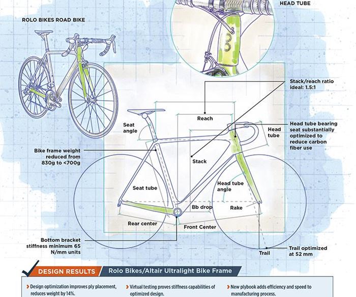
Design Results:
- Design optimization improves ply placement, reduces weight by 14%.
- Virtual testing proves stiffness capabilities of optimized design.
- New plybook adds efficiency and speed to manufacturing process.
The modern bicycle was conceived and developed around 1820 by a German named Baron Karl von Drais, who built the draisine, a 22-kg, pedal-less, wood-framed, iron-wheeled vehicle that riders propelled simply by ‘walking’ while astride the bike frame. It featured a hand-activated brake on the back wheel. Drais reported that he could ride his draisine over a distance of 13 km in less than one hour.
Since then, inventors have added a chain-and-sprocket drive, crankshaft and pedals, put brakes on the front wheel, modified wheel sizes, developed rubber tires, improved seat design and employed lightweight materials, the latter culminating, today, in the dominance, on the market’s high end, of aluminum and carbon fiber composites. Along the way, the bicycle has become the most efficient and fastest form of human-powered transport.
As bicycle materials and technology improved, bicycle design matured. Today, it revolves primarily around two factors: Weight reduction and rider comfort/ergonomics. The former has reached its zenith in all-carbon fiber composite bike frames, for which riders pay a high premium — similar to that paid for carbon fiber use in high-end automobiles. The latter have focused on optimizing the transfer of human muscle power to the crankshaft.
Despite these advancements, however, carbon fiber bike frame design and manufacture has largely mirrored that employed for steel and aluminum: a series of mass-produced tubes that are subsequently bonded together (aka, “black aluminum”). The bike manufacturer is rare who has developed a single-piece, monococque carbon fiber frame. And until recently it was virtually impossible to find a bike manufacturer who has designed, developed and manufactured such a frame optimized specifically to use carbon fiber composites.
That is, until Rolo Bikes (Luxembourg; Stockholm, Sweden) met Altair Engineering Inc. (Troy, MI, US).
Designing the perfect bicycle
Rolo Bikes was founded by Adam Wais, who is not a lifelong cyclist. But, his friend Anders Annerstedt is. Wais and Annerstedt, says Wais, found themselves talking more and more about bikes and biking, and about current bicycle design and materials. Wais eventually broke down and decided to get a road bike.
This raised a difficult question for Wais: “What really matters in a bike? What is the hierarchy of importance? How do we evaluate bike quality?” The short answer was simple: Fit, handling and engineering. But he could not find a bike with the fit, handling and engineering he desired. Thus, Rolo Bikes was launched in 2011.
Rolo’s mission is simply stated, but complex in execution: Design a bike frame that optimizes rider comfort and pedaling efficiency, applying carbon fiber in a way that maximizes material application while minimizing weight. This would require a holistic, back-to-basics design assessment, says Wais. “We started,” he says, “by looking at the relationship between the three human contact points on a bike: The saddle, handle bars and pedals.”
One data point emerged as critically important in overall frame design: the stack/reach ratio. The stack is the vertical distance from the bottom bracket (crankshaft) to the top of the head tube. The reach is the horizontal distance from bottom bracket to the top of the head tube (see drawing below). If this ratio is low, the rider is more stretched out over the bike (less comfortable), but also in a better aerodynamic profile. If stack/reach ratio is high, the rider sits more upright (more comfortable), but in a less aerodynamic profile.
A variable in this ratio is body type — leg, torso, arm length — but Rolo’s research, says Wais, revealed that regardless of body type, most people have bodies that are, statistically, proportional. So, the question became, “What is the ideal stack/reach ratio?” Rolo’s answer is 1.5:1. This number offers the best balance of comfort and aerodynamics.
Next, Rolo evaluated an apparently trivial design feature that actually has significant impact on bike performance. Called the trail (see drawing), it’s the imaginary distance on the ground created by the angle between the head tube and an imaginary vertical line through the front hub. A long trail is more self-stabilizing, but makes wheel turning more difficult. A shorter trail tends to create wheel flutter. So, what is the ideal trail? Rolo says 52 mm, which is relatively short. Says Wais, “We opted for a low-trail bike, which feels twitchy at first, but as speed increases, handling gets much easier.”
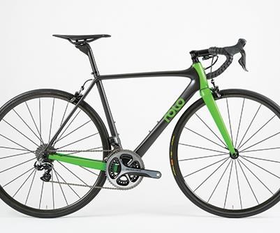
With these data in mind, says Wais, Rolo developed its first carbon fiber monococque bike frame, designed in Dassault Systèmes' (Waltham, MA, US) SolidWorks. The result, based on M55J UD and M46J twill epoxy/carbon fiber prepreg (Toray Carbon Fibers Europe, Paris, France), hand-laid in a metallic mold with bladder core and cured in an autoclave, was estimated to weigh 830g.
Making good even better
Rolo and Wais, however, weren’t done designing. The lightest bikes in the world have frames of less than 700g, and Rolo had to be able to compete at that level.
Wais says conventional bicycle development involves making several prototypes and then testing each to determine which design performs best. Most critical in this process is that the frame meet certain strength and stiffness requirements established by the Zedler Institute (Ludwigsburg, Germany). Designing a frame at a competitive weight that also could pass the Zedler tests would be a real challenge.
Wais wanted to limit as much as possible, if not eliminate, this expensive trial-and-error development process: “I refused to believe that there weren’t tools out there that allowed us to do all of the design work virtually.”
With that in mind, he started asking around the composites industry and, eventually, settled on Altair Engineering (Troy, MI, US). “We went to Altair and said, ‘We really need your help and we want to be smart about this,’” Wais recalls. Rolo also did not want to invest the money, time and intellectual capital required to acquire and learn to use design simulation software. So, it opted to use Altair’s design services. That’s when Altair’s team manager, Kate Fisher, entered the picture.
Working remotely and in person with Rolo engineers, Fisher says she first created a virtual test structure that emulates the type used in Zedler tests. Into it, she placed a finite element model of the Rolo frame. Next, she looked at strength and stiffness targets set by Wais:
• Bottom bracket stiffness: >65 N/mm
• Head tube stiffness: >96 Nm/deg
The design optimization process, performed using Altair’s OptiStruct product, followed three steps. First, starting with a 0°/±45°/90° ply schedule, Fisher conducted what’s called free element sizing, which basically determines where on the frame plies should be placed to meet stiffness targets. The result, she says, is an “organic-looking patchy structure” that highlights the frame’s fundamental design elements.
Second, Fisher conducted sizing, which is an assessment of how much material to put where to create the thicknesses required. This step, she says, depends on the type of prepreg used. “The first two stages are the most crucial: Where to put each material — and how much,” she says.
The third and final step is sequencing — a shuffling of the ply order to fine-tune stiffness and to avoid consecutive plies oriented in the same direction.
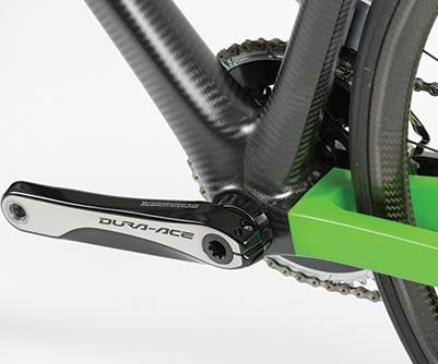
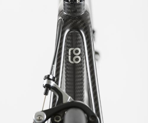
Most of the optimization, say Fisher and Wais, was in the head tube and bottom bracket, which suffered in the original design from less-than-adequate reinforcement application. Says Fisher: “The additional [optimized] mass that was added in the thickest areas was compensated for by taking out material in other, less-critical areas.”
“Once these steps were done, we went back to our virtual test rig to see how the design performed,” Fisher says. In short, it passed. Not only that, but the new frame checked in at <700g, 14% lighter than its baseline predecessor. “More importantly,” reports Fisher, “we now have a design that is much easier to manufacture. Plies are relatively large and edges are very clear and easy to see and place.”
Proof in the prototypes
With a new, optimized design and new plybook in hand, Rolo then went to work proving that the virtual results could be replicated in the real world. “We had a reasonable idea from the simulation that the prototypes would be pretty close,” says Wais. Indeed, although the new design required a few “tweaks,” on the whole, they matched up well. “The target we set for the head tube stiffness was over 96 Nm/deg, and the bottom bracket stiffness target was over 65 N/mm,” says Wais. “We are on target for the head tube and way over on the bottom bracket.”
Further, with the design simulation process proven, Rolo has simplified its manufacturing path for future bikes. The entire process, first time around, says Fisher, took about five weeks. “The most difficult part is building your virtual test rig and making sure that the baseline design is robust,” Fisher says. “Once these things are in place, it becomes a much easier process.”
“Now, based on what we know,” says Wais. “I think we would be pretty confident going straight from simulation right to production tooling with only minor modifications.”
With the optimized design and more efficient manufacturing process that results, Wais hopes to drive down overall cost. As a result, a fully assembled Rolo bike today runs €14,000-€15,000 (US$15,900-US$17,000), but Wais thinks he can bring the bike’s price point down to €11,000 (US$12,500).
“There is so much we can simulate,” Wais says, thinking about the future. “We are only at the very beginning.”
Related Content
PEEK vs. PEKK vs. PAEK and continuous compression molding
Suppliers of thermoplastics and carbon fiber chime in regarding PEEK vs. PEKK, and now PAEK, as well as in-situ consolidation — the supply chain for thermoplastic tape composites continues to evolve.
Read MoreThe potential for thermoplastic composite nacelles
Collins Aerospace draws on global team, decades of experience to demonstrate large, curved AFP and welded structures for the next generation of aircraft.
Read MoreComposites manufacturing for general aviation aircraft
General aviation, certified and experimental, has increasingly embraced composites over the decades, a path further driven by leveraged innovation in materials and processes and the evolving AAM market.
Read MorePlant tour: Teijin Carbon America Inc., Greenwood, S.C., U.S.
In 2018, Teijin broke ground on a facility that is reportedly the largest capacity carbon fiber line currently in existence. The line has been fully functional for nearly two years and has plenty of room for expansion.
Read MoreRead Next
Developing bonded composite repair for ships, offshore units
Bureau Veritas and industry partners issue guidelines and pave the way for certification via StrengthBond Offshore project.
Read MorePlant tour: Daher Shap’in TechCenter and composites production plant, Saint-Aignan-de-Grandlieu, France
Co-located R&D and production advance OOA thermosets, thermoplastics, welding, recycling and digital technologies for faster processing and certification of lighter, more sustainable composites.
Read More“Structured air” TPS safeguards composite structures
Powered by an 85% air/15% pure polyimide aerogel, Blueshift’s novel material system protects structures during transient thermal events from -200°C to beyond 2400°C for rockets, battery boxes and more.
Read More

