Composite fan blade containment case
Innovative use of carbon-fiber braid yields a ductile structure that resists blade impact.
One of the many challenges facing the jet engine designer is to contain a failed fan blade within the engine, so that it threatens neither passengers nor airframe. Not only does the fan case structure have to withstand the blade impact, but it must also retain its structural integrity while the engine is shutting down. After an engine loses a blade, the loads on the fan case rise, well above those experienced in normal flight, due to the fan imbalance. During engine shut down, typically 15 seconds, cracks can propagate rapidly in the fan case from the damage caused by the impact of the broken blade. If the fan case were to fail completely, then the consequences for the engine and aircraft could be catastrophic.
There are two approaches to blade containment currently in common use. One, the softwall fan case, features a casing of aluminum, over-wound with dry aramid fibers. It is designed to permit a broken blade to pass through its aluminum component, where it is stopped and contained within the external aramid fiber wrap. The other type, the hardwall fan case, is aluminum only and is designed to reflect the blade back into the engine. The hardwall concept enables designers to improve engine aerodynamics by building a case with a smaller radial envelope, since no "dead" space is required for deflection of an aramid wrap. However, there is the risk that the broken blade may pass through the engine, with the potential for secondary damage well in excess of that experienced in the softwall design. The key material properties are the ductility of the metal cases and, in the case of the softwall system, the energy absorbing capabilities of the aramid fibers.
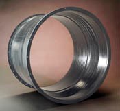
A carbon composite casing would save weight, but could it be designed to behave in a ductile manner during a blade impact? This is the question being answered by A&P Technology (Cincinnati, Ohio) and the NASA Glenn Research Center (GRC, Cleveland, Ohio) in a project funded by the NASA Aviation Safety and Security Program. NASA research into both softwall and hardwall configurations has led to a new generation of carbon fiber-reinforced polymer (CFRP), which promises to match the strength and ductility properties of a ductile metal casing but at a much lower weight. The key component is its reinforcement, a triaxial braid developed by A&P. The braid architecture is very resistant to delaminations between plies. Since all fiber orientations are present within each ply, all plies are identical. The stiffness match at ply interfaces, therefore, results in inherent structural toughness. Furthermore, the triaxial fiber architecture limits linear crack propagation, confining failure to very limited regions.
Development program
NASA GRC began research on impact testing and analysis of engine fan case structures in 1994 as part of the Enabling Propulsion Materials (EPM) Program. The Ballistic Impact Laboratory facilities at NASA were used to test various metallic materials and structural concepts for a lightweight fan containment case. In addition, research was begun on methods used to analyze and test metal-based designs to adapt them for use with composite case designs. Research on polymer composites as a lightweight alternative to metal fan cases was expanded at NASA in 1998 with the beginning of the Ultrasafe Program (Susan Johnson, program manager; Dale Hopkins, technical team leader). NASA GRC's materials research engineer Gary Roberts led a research project to develop the new generation of composite fan case materials, to demonstrate improved containment capability and damage tolerance for composite materials; demonstrate commercial feasibility; and mitigate the risk of using the new composite technology. A&P Technology's Mike Braley demonstrated the containment capability, damage tolerance and commercial feasibility of a braided reinforcement during a NASA-sponsored SBIR Program. NASA initiated several research efforts to reduce risk, which included improving the fidelity of the design process. This was accomplished, in part, by integrating reliable composite material models into the explicit finite element codes currently used for blade-out analysis on metal-based cases, to adapt them for impact simulation scenarios with composite containment cases. NASA also sought a new approach to ballistic impact testing and post-impact structural loading that could simulate critical loads during a blade-out test. A further program goal was to identify new nondestructive evaluation (NDE) and nondestructive inspection (NDI) methods for the braided composite structures.
Researchers at the University of Akron (Ohio), Ohio State University and Arizona State University have provided critical support for the NASA research. In 2003, Roberts began extending the successful research performed during the Ultrasafe Program to higher technology readiness levels (TRLs) in the NASA Aviation Safety and Security Program (AvSSP). In a third SBIR effort, A&P Technology is currently partnered with engine manufacturers to apply the braided composite materials to specific fan case designs and their individual performance requirements. NASA is planning to perform impact testing and post-impact loading on composite fan cases from the SBIR program. Data from these tests will further validate the fidelity of the composite material models and design tools being developed by researchers.
Testing
Impact tests need to be performed in a manner that replicates the blade-to-case impact dynamics that are likely to occur in an actual engine blade failure. In order to achieve this, researchers had to develop a new understanding of blade trajectory in blade-out scenarios. This was undertaken by Kelly Carney at NASA and Wieslaw Binienda at The University of Akron (Ohio), using LS-DYNA, a unique analytical code developed by Livermore Software Technology Corp. (Livermore, Calif.). Results were used to analyze and predict the blade dynamics during a blade out event, as well as to predict the impact events. The complicated paths taken by the blade — involving not only their linear speed and direction but rotational motion as well — are then used as the basis for determining the impact scenario in the ballistic tests.
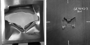
In earlier work at NASA, damage testing was initially undertaken on flat panels to compare the CFRP panels with aluminum panels, using an air gun, with gelatin packs and then metal blade simulators as the projectiles. A comparison of the hole sizes generated in a composite panel with that in the datum aluminum panel (representing a typical metal fan case) was very encouraging, since the much smaller hole created in the CFRP structure indicated that there would be a reduction in the stress level in a blade-damaged CFRP fan case, when out-of-balance loads were inflicted by an asymmetric fan.
Encouraged by this success, NASA will test a full-size case in a later phase of the program. After the initial blade impact test, the fan case will be loaded in a manner similar to that experienced during the post blade-loss regime. This involves a cyclic fatigue test representing the number of cycles experienced by the damaged case during engine shutdown. Measurement of damage propagation then will be analyzed and used to develop the capability to predict success or failure of the containment casing.
It is expected that the CFRP case will be more successful than the metal case, with the naturally good crack resisting properties of the braided structure being sufficient to maintain the case's residual integrity.
Manufacturing automation
When replacing aluminum with CFRP, weight savings are achieved, but few applications can justify a significant cost premium for the lighter weight. Triaxial braiding provided an automated method of laying up the fibers in the correct orientation. Various infusion processes will provide a method of impregnating the resin into the fibers at minimum recurring cost. However the task of laying up a preform from dry fibers is not easy, particularly when the structure is a complex cylinder, made more difficult by the integrated end flanges in the design.
Because the application of this technology is targeted at a number of different engine companies, each with its own supply base, NASA needed an automated method of laying up a robust preform that subsequently could be shipped to a variety of composite fabricators for conversion into a composite component.
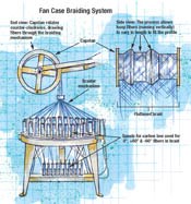
A&P's solution for this requirement was ingenious. First, a triaxial braider, mounted with the axis vertical, creates a braid that then is flattened into a double-walled tape, with fibers at 0° and, typically, ±60°. The braid is designed so that, when flattened, it is the correct width to cover the developed length of the fan case and the flanges. The flat tape is wound around a capstan that incorporates the profile of the particular containment case for which the braid is intended. Because the part profile varies in diameter, particularly in flange areas, hoop (circumferential) fiber lengths in the fan case should differ. Therefore, if a conventional woven cloth or even a piece of pre-made braid were used, in which the axial or longitudinal fibers would be identical in length across the material width, then the perform would tend to wrinkle where the case diameter narrowed. A&P's triaxial braid, however, is formed in close proximity to the capstan, as it is being wound onto the capstan. As the capstan turns, the tows that form the braid are drawn from spools through the braiding apparatus. This arrange- ment permits the lengths of individual axial tows, which become the hoop fibers in the finished case, to be drawn at different rates from their spools. The length of each tow is determined independently of the others, as it is drawn around the capstan's cir-cumference. In this way a component with varying diameters along its length can have a reinforcement with straight hoop fibers at all points, including the most critical area of the flanges.
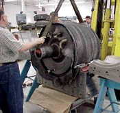
The capstan is rotated until the required number of plies for each preform is achieved, typically 10, but equivalent to 20 plies of woven material, because the flattened tube forms two layers. The completed, preform is then transferred from the capstan to a lightweight cylinder for transport to the fan case fabricator. When wound on the transport cylinder, the preform maintains the cross-sectional geometry it acquired on the capstan, because there is sufficient friction between the circumferential and bias fibers to prevent slippage that would result in deformation.
After it is shipped to the component fabricator, the preform is simply wound onto the mandrel of a mold tool, where it is impregnated with resin via resin transfer molding (RTM) or vacuum-assisted RTM (VARTM), whichever is chosen by the part manufacturer. Although the process can incorporate a variety of fiber and resin types, the materials used in the program were T-700 12K carbon fiber, supplied by Toray Composites America (Tacoma, Wash.), and EPON 862 bisphenol F-based epoxy resin, a toughened system (10 percent elongation) formulated for high resistance to fatigue and microcracking by Resolution Performance Products (Houston, Texas). The molding was undertaken by North Coast Composites (Cleveland, Ohio).
Future work
The technology has been successfully demonstrated for the hardwall-type case and may find its first application on a turbofan jet engine built by Williams International (Walled Lake, Mich.). Jim Dorer, William's Compression DTP team engineering specialist, believes the company may achieve up to a 40 percent weight saving over the metallic datum. Assuming this can be achieved at an acceptable cost, the technology could be launched on a new family of jet engines currently under development at Williams.
Meanwhile, a third program phase has been initiated to further explore the manufacture of softwall fan cases. Two softwall structures were manufactured during the earlier program phase. Such cases are usually constructed with a honeycomb cored sandwich structure. This would preclude the use an infusion process. Alternative foam cores are now being studied to determine if they will perform correctly during infusion and impact tests. This technology is being applied to large fan cases, up to 9.1m/3 ft in diameter, manufactured by the RTM process.
Related Content
PEEK vs. PEKK vs. PAEK and continuous compression molding
Suppliers of thermoplastics and carbon fiber chime in regarding PEEK vs. PEKK, and now PAEK, as well as in-situ consolidation — the supply chain for thermoplastic tape composites continues to evolve.
Read MoreBraskem demonstrates PP solutions using Weav3D composite lattice technology
Partnership combines Braskem’s polypropylene sheets with Weav3D Rebar for Plastics technology to address new structural, automotive applications requiring high-strength, lightweight material solutions.
Read MorePlant tour: Albany Engineered Composites, Rochester, N.H., U.S.
Efficient, high-quality, well-controlled composites manufacturing at volume is the mantra for this 3D weaving specialist.
Read More3D-woven composites find success in aerospace, space
CAMX 2024: Bally Ribbon Mills experts are displaying the company’s various joints, thermal protection system (TPS) technologies and other 3D woven composites for mission-critical applications.
Read MoreRead Next
“Structured air” TPS safeguards composite structures
Powered by an 85% air/15% pure polyimide aerogel, Blueshift’s novel material system protects structures during transient thermal events from -200°C to beyond 2400°C for rockets, battery boxes and more.
Read MoreVIDEO: High-volume processing for fiberglass components
Cannon Ergos, a company specializing in high-ton presses and equipment for composites fabrication and plastics processing, displayed automotive and industrial components at CAMX 2024.
Read MoreDeveloping bonded composite repair for ships, offshore units
Bureau Veritas and industry partners issue guidelines and pave the way for certification via StrengthBond Offshore project.
Read More


