Composites enable portability in driving simulator
FRP design enables portable, light-tight, enclosure with an image-projection-grade inner surface.
Design results:
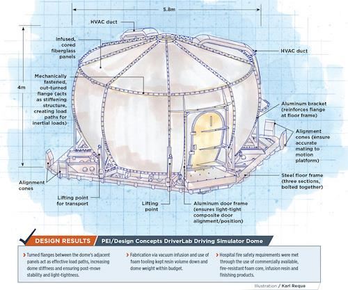
- Turned flanges between the dome’s adjacent panels act as effective load paths, increasing dome stiffness and ensuring post-move stability and light-tightness.
- Fabrication via vacuum infusion and use of foam tooling kept resin volume down and dome weight within budget.
- Hospital fire safety requirements were met through the use of commercially available, fire-resistant foam core, infusion resin and finishing products.
Devices that simulate the reality of operating complex machines have become important and increasingly sophisticated tools in applications as diverse as pilot flight training, driver response/ reaction research and virtual reality games. Composite materials play an important role in this growing niche market, enabling lightweight, dome-shaped enclosures with support structures that accommodate arrays of projection equipment and motion controllers.
Pagnotta Engineering Inc. (PEI, Exton, PA, US) has a long history and a reputation for excellence in flight simulator design and construction. Recently the company and partner JRL Ventures
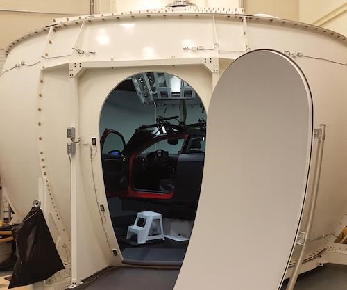
LLC (dba Design Concepts, Cape Coral, FL, US) collaborated on a driving simulator dome (Fig. 1, below) — a first for both — for the Toronto Rehabilitation Institute, University Health Network’s (TRI- UHN, Toronto, ON, Canada) Challenging Environment Assessment Lab (CEAL). Inside the dome, dubbed DriverLab, the driving skills of older people and those with illnesses will be assessed under many conditions, as a means to evaluate the impact of TRI-UHN- developed patient treatments.
Designing within many constraints
“Images projected onto screens surround the driver, who will actually be ‘driving’ a specially modified Audi A3, which sits on a turntable inside the composite dome, which in turn is mounted on a motion-control platform,” explains PEI engineering manager, Alex DiEdwardo.
To stay within the overall payload capacity of the motion system (car included), the weight budget for the PEI-designed and JRL- fabricated deliverables was limited to 3,000 kg. That covered a 5.8m diameter, 4m tall, fiber-reinforced polymer (FRP) projection dome, HVAC (heating, ventilating and air conditioning) ducts and a steel floor frame, with overhead lifting fixtures and mounts for power and motion control.
“This limited the weight of the FRP dome and HVAC ducts to just under 1,000 kg,” says DiEdwardo. In addition, the structure had to be stiff enough to resist buckling and maintain a fundamental natural frequency above 15 Hz, to prevent excitation caused by the energy input of the motion platform.
In terms of laminate strength, PEI determined that typical designs for aircraft flight simulators, which must withstand 2.5G quasi-static accelerations in any direction, combined with 1G gravity, would be sufficient, explains DiEdwardo. “These values are much higher than the typical operational loads, and are specified to protect occupants from a software-driven motion system failure or a hydraulic strut failure.”
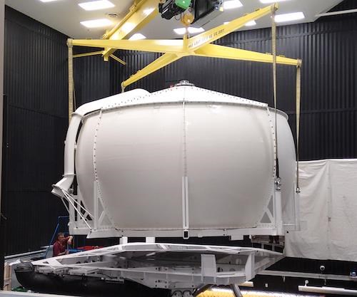
A big challenge was the fact that DriverLab would be routinely exchanged for four other lab modules that would share a common 6m by 6m, six-degrees-of-freedom hydraulic motion platform, so the simulator structure had to be capable of being unbolted from the platform, lifted and moved (Fig. 2), with no risk of over-turning. Thus, the design had to account for stresses in the entire structure, including the metallic floor frame, taking into account the dome’s access door, for lifting load cases as well as overturning stability, says DiEdwardo.
“From our past experience working on a swappable payload flight simulator at NASA Langley,” he says, “we knew that lifting stresses can really influence the design of the dome components, due especially to the flexure of the floor frame during lifting.” Those stresses meant that the dome’s access door would require extra attention, to maintain a light-tight seal after moves.
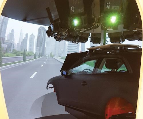
The dome’s interior wall (the tool-side surface) would function as the image projection surface. Strict requirements for that surface and the projection system’s optics were provided by International Development of Technology (Breda, The Netherlands), the simulation engineering firm contracted by TRI-UHN to develop the DriverLab’s technical specifications. Those requirements drove PEI to design the dome in a toroidal shape, with an upper cap (see drawing) to allow sufficient surface area for the multiple projection scenarios. Laminate finish requirements were strict in terms of smoothness to ensure quality of the projected graphics on the composite surface (Fig. 3), so manufacturability and tool quality needed careful consideration during the design phase. Lastly, driving simulations would include water sprayed onto the car inside the dome to simulate rain, so the floor element had to be designed to capture and drain the water.
Keeping weight and costs low
The dome structure’s FE model was created using Femap software for pre- and post-processing, together with NX Nastran (both supplied by Siemens PLM Software Inc., Plano, TX, US). The modeling software enabled static, quasi-static and modal (natural frequency) analyses, and determination of maximum dynamic loads and stresses due to the motion platform and lifting scenarios, so that design factors of safety could be applied. The software’s buckling eigenvalue solution module and classical engineering equations helped PEI ensure buckling factors of safety were met, says DiEdwardo, and ultimately resulted in the dome’s laminate architecture, which would consist of cored fiber- glass sandwich segments bolted together with metallic fasteners.
“Our solution to get the strength and stiffness that we needed was to construct the segments with [out-]turned flanges bolted together, to act as stiffening structure and provide a smooth inner surface,” explains DiEdwardo. “The thick, uncored flanges are very effective in providing an efficient load path for inertial loads from the projectors, and from the motion-control platform, and allowed us to keep the cored field regions of the dome and cap very light in weight, while keeping construction simple.” He adds that flanges were reinforced with aluminum brackets where they connected to the floor frame and to the projector mount in the dome cap.
Trade studies were conducted to optimize the FRP laminate thickness and number of skin plies, ply orientations, and core density and thickness for the segments. The trade studies also helped optimize the metal floor frame-member sections for strength and stiffness, as well as ease of shipping and installation. The final design of the frame comprised three sections that bolt together.
Although the fiber architecture details are proprietary, ±45° biaxial noncrimp glass fabrics from Vectorply Corp. (Phenix City, AL, US) were selected for the skins, because they would best handle the shear loads over the dome’s cored field regions, a conclusion confirmed by the FE model. “Because this simulator would operate in the basement of a hospital building, it had to meet building fire codes,” DiEdwardo adds, particularly to avoid fire spread to upper floors. Therefore, Airex foam core material, 13-19 mm thick and supplied by 3A Composites (Colfax, NC, US), was chosen for its fire-retardant properties. AOC’s (Collierville, TN, US) Firepel polyester infusion resin, also was selected, in part, for its fire-resistance properties.
DiEdwardo reports that early manufacturing discussions with Design Concepts focused on keeping costs down through open mold/hand layup. But as the design matured, it became apparent that the weight budget would be tough to meet by that route. Design Concepts suggested that vacuum-infusing the parts, which typically costs more than hand layup, would better control resin volume and, therefore, part weight.
To keep infusion costs as low as possible, Design Concepts CNC-machined the molds for each segment from expanded polystyrene (EPS) foam. The shaped EPS was sheathed with fiberglass and resin, then overlaid with syntactic, which was machined to the final dimensions of the dome’s inside surface. Given the small part count, the low-cost foam molds saved time and cost but posed the potential for lack of vacuum integrity during infusion. That problem was solved with Diamondback tooling gel coat from Polycryl Corp. (Oakland, TN, US). For the production parts, Hawkeye Industries Inc. (Bloomington, CA, US) Duratech vinyl ester in-mold primer was applied over the prepped mold surfaces prior to dry layup, to enable cured parts to be painted with fire-resistant paint.
Before final parts were fabricated, PEI and Design Concepts infused test panels using the selected materials and performed coupon-level B-basis tension, compression and shear strength tests in accordance with ASTM International (W. Conshohocken, PA, US) methods. Says DiEdwardo, “Stresses determined using the FE model were compared to the test allowables to ensure we would get the performance we needed from the structure.”
One of the project’s biggest challenges was the door and door frame design, says DiEdwardo. “It’s tough when designing simulators to replace the lost stiffness when you have to cut an aperture in the structure,” he explains. The door frame was designed around existing hard points on the motion platform, and includes an additional aluminum frame, mechanically attached to the dome segment via post-bonded flat FRP panels (see drawing).
The composite door itself was hand-fitted to the frame by Design Concepts’ technicians, to ensure the seal was light-tight for best projection performance, and the frame serves as a stiffening element to help keep the door alignment consistent.
A unique product
“The FRP weight ended up being 1,000 kg, including ventilation ducting,” DiEdwardo reports, ”so we met the weight requirements without issue and also used cost-effective materials to meet the cost budget.” The dome also successfully completed factory accep- tance testing by IDT and TRI-UHN prior to installation. And the fully outfitted DriverLab was finally lowered through floor grates in front of the TRI-UHN hospital into CEAL’s underground research facility in August of this year.
PEI is hopeful that the success of DriverLab will open up new opportunities for more driving simulators.
Related Content
Pultrusion: The basics
A primer describing what pultrusion is, its advantages and disadvantages, and typical applications.
Read MorePEEK vs. PEKK vs. PAEK and continuous compression molding
Suppliers of thermoplastics and carbon fiber chime in regarding PEEK vs. PEKK, and now PAEK, as well as in-situ consolidation — the supply chain for thermoplastic tape composites continues to evolve.
Read MoreJeep all-composite roof receivers achieve steel performance at low mass
Ultrashort carbon fiber/PPA replaces steel on rooftop brackets to hold Jeep soft tops, hardtops.
Read MoreCombining multifunctional thermoplastic composites, additive manufacturing for next-gen airframe structures
The DOMMINIO project combines AFP with 3D printed gyroid cores, embedded SHM sensors and smart materials for induction-driven disassembly of parts at end of life.
Read MoreRead Next
Developing bonded composite repair for ships, offshore units
Bureau Veritas and industry partners issue guidelines and pave the way for certification via StrengthBond Offshore project.
Read More“Structured air” TPS safeguards composite structures
Powered by an 85% air/15% pure polyimide aerogel, Blueshift’s novel material system protects structures during transient thermal events from -200°C to beyond 2400°C for rockets, battery boxes and more.
Read MoreAll-recycled, needle-punched nonwoven CFRP slashes carbon footprint of Formula 2 seat
Dallara and Tenowo collaborate to produce a race-ready Formula 2 seat using recycled carbon fiber, reducing CO2 emissions by 97.5% compared to virgin materials.
Read More


