Cost-effective carbon composite reflector dish
Modular manufacturing method forms different dish sizes with near mirror-perfect reflective surfaces, without resort to one-off tools.
Share
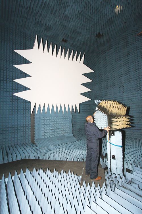
Development of wireless communications equipment, radomes, aircraft, satellites, missile systems, stealth technology and radar countermeasures traditionally required far-field testing, in which a radar device and its target, or a feed antenna and the antenna under test (AUT), were placed a great distance apart. Typically, a test range spanned thousands of feet. For practical reasons, such testing was done outdoors. Today, however, testing also can be done in a compact range, where a special reflector is used to make the radar device or feed antenna appear to be an infinite distance from the target or AUT, enabling simulation of an outdoor far-field test, using a more cost-effective, near-field test method within an enclosed facility. As a result, test security is improved and test technicians have greater control over test conditions.
Beaufort Composite Technologies (BCT, Beaufort, N.C.) was one of two companies short-listed by a leading supplier to manufacture five compact range (CR) reflectors using composites instead of steel or aluminum. But the order included several reflector models, each of which would be built to a different size. Conventional practice would require that each composite reflector be pulled from a unique tool, with each tool painstakingly created to very tight surface tolerances. Specifically, the reflector surface smoothness had to be within 0.0006 inch/0.015 mm (approximately one-seventh the thickness of a sheet of paper), or as commonly described in the industry, the surface accuracy was 0.0006-inch/0.015-mm RMS (root mean square). It was a scenario likely to price the reflectors out of contention during the bidding process.
In search of a more cost-effective manufacturing method that might increase BCT’s potential to field the winning bid, company president Phil Herting designed a modular construction method that enabled his company to fabricate reflectors of a given focal length in multiple sizes, using lightweight, rigid carbon-fiber composites, without building one-off tooling for each reflector. He also developed a technique for producing each reflector’s paraboloid surface to very stringent smoothness tolerances. These efforts were successful and secured not only the job at hand, but a multiyear contract as well.
Almost infinite scalability
An experienced composites manufacturer in a wide variety of industries, including medical, aerospace, automotive and defense, BCT has specialized in design and engineering development for complex shapes and assemblies, using primarily advanced fiber/epoxy prepreg and cored sandwich construction. The company also had a long track record in resolving tooling and process challenges, a history that served it well as Herting and his team confronted the CR reflectors and put together the winning bid.
A CR reflector is housed in a compact range facility that typically consists of a temperature-controlled rectangular chamber lined with radar-absorbing material to minimize reflection. The reflector has either rolled or (in the case reviewed here) serrated edges that minimize and/or direct edge diffraction away from the target area (also known as the quiet zone). CR reflectors are often rectangular, but there also are compact ranges equipped with circular, semicircular and elliptical reflectors. Reflector size can range from a few square feet to 50 ft by 75 ft (15m by 23m) or larger. The reflector’s parabolic surface must be extremely smooth, but it also must be supported by an extremely stiff backing structure to ensure the accuracy of the reflector’s compound curvature, vital for radar cross section (RCS) and other measurements.
BCT began work on its reflector design by acquiring focal length and overall size specifications from its customer, and then developed the surface geometry, using basic mathematical equations that govern parabolic shapes. The surface and support structures were modeled using Strand7 finite element analysis (FEA) software, supplied by Strand7 Pty. Ltd. (Sydney, Australia).
According to Herting, the design and analysis process required expertise and close attention to tedious detail, but was primarily a matter of understanding and applying fundamental mathematics. The real challenge, however, was to transform the design into a physical structure. From the outset, that task was considered beyond the reach of conventional molding practice. “There is no tool that could maintain the accuracy required for the surface and still be cost-competitive in this market,” he explains. That fact opened up the alternative of molding the reflector surface in smaller sections, which would allow BCT to assemble reflectors in a variety of sizes. However, this modular approach still presented significant challenges. “The inherent nature of parabolic shapes means there are no repeatable parts,” he explains. “In other, words, if you apply a grid to the reflector surface, no two areas on the surface are the same.”
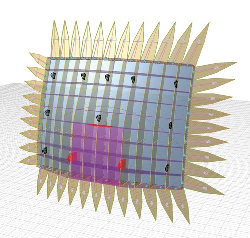
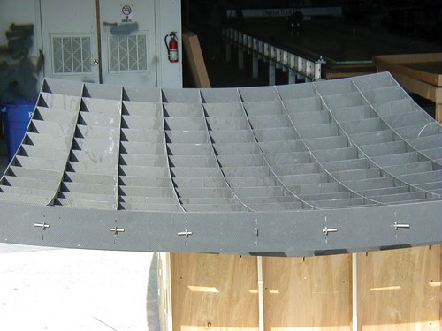
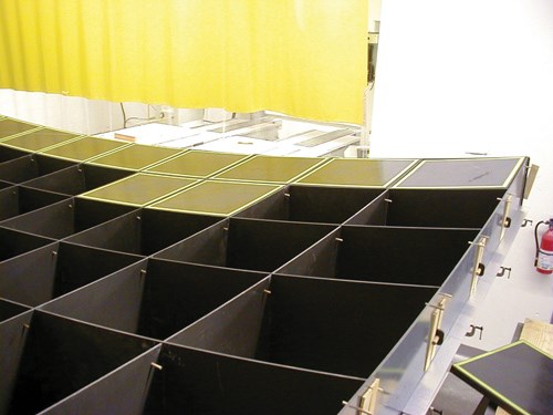
Herting’s breakthrough was to approximate the reflector surface, by using the closest-fit spherical shape, which could then be segmented into a finite number of composite face plugs, easily produced using a multiple-cavity mold. “For one of our recent dishes with a body size of 11 ft by 8.5 ft [3.4m by 2.6m] and a 144-inch [3.7m] focal length,” Herting illustrates, “we used a mold with eight cavities and cycled it 18 times to produce all of the surface parts/face plugs.” To support the segmented surface components, Herting devised an egg-crate-style backing structure, assembled from pre-cut flat stock, that receives the molded face plugs and aligns them in proper relation to one another, thus approximating the reflector dish surface.
Because the reflectors are very sensitive to anything that may cause signal deflections, such as changes in temperature that cause expansion or contraction, BCT elected to use carbon-fiber-reinforced polymer (CFRP) for the backing structure and face plugs. The CFRP construction not only promised an extremely stable coefficient of thermal expansion (CTE), but also offered several other advantages over aluminum and steel, including reduced part weight and greater structural stiffness. “By breaking up the part in this way,” Herting points out, “we have an almost infinitely scalable manufacturing method plus a super-stiff structure without size-dependent tooling.” To achieve the final parabolic shape, the assembled composite structure would be coated with a layer of epoxy tooling paste, which would permit BCT to machine the surface to final tolerance.
In the final stage of the design process, BCT programmed cutting software for BCT’s DCS 2300 static cutter (Gerber Technology, Tolland, Conn.), which would cut prepreg plies for the molded face plug laminates. Plies also would be cut for CFRP angle stock that would be adhesively bonded into the egg-crate interstices, effectively locking the latticework into place.
Fabricating shapes and pieces
The bid-winning design has since proved its worth in actual production. For the curved face plugs, cut and kitted prepreg plies are layed into a multicavity, computer-controlled, heated face plug mold. The face plugs use 2x2 twill fabric/epoxy prepreg supplied by Gurit (Isle of Wight, U.K.), made from 3K and 12K carbon fiber. The fabric’s conformability helps to produce the wide variety of curved surfaces. However, the first ply is an impregnated peel ply which eliminates having to grind the back façade before bonding it into the egg-crate lattice. This ply also provides a top surface to which the epoxy tooling paste can easily adhere.
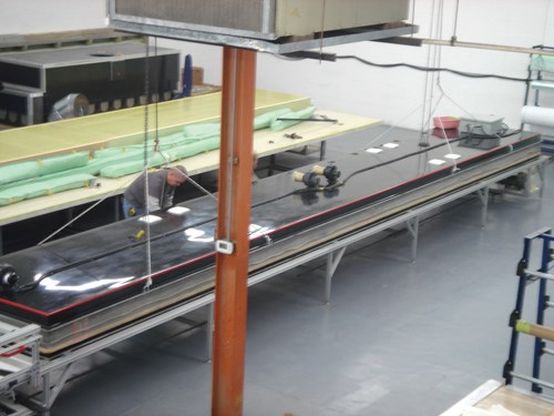
The flat stock from which the egg-crate structural lattice pieces and the pointed serrations are cut is formed using prepreg, but is cured in a BCT-designed-and-built vacuum press, capable of producing 4-ft by 32-ft (1.2m by 9.8m) panels up to 6 inches/152 mm thick. The egg-crate and serration flat-stock uses a quasi-isotropic layup made with a 3K 2x2 twill, 300 g/m² (9 oz/yd²) and 600 g/m² (18 oz/yd²) unidirectional and 600 g/m² (18 oz/yd²) double-bias prepreg plies, also supplied by Gurit.
The thickness of the egg-crate flat-stock varies with reflector size. For example, a smaller reflector might use a nominal 0.125-inch/3.175-mm thick laminate while a larger size might require twice that thickness. In the recently produced reflector noted above, for example, the egg-crate stock required 10 plies while the serration stock used a seven-ply quasi-isotropic layup on either side of a 5 lb/ft³ (0.08 g/cm³) Corecell T-Foam supplied by Gurit.
A carriage system runs the length of the press, enabling precise application of plies, including 32-ft/9.8m lengths of continuous unidirectional prepreg, which makes a big contribution to efficiency during production of egg-crate structural ribs for large reflectors. The integrally heated tool faces are prepared with a Teflon release supplied by Taconic International Ltd. (Mullingar, Ireland), and 12 independently computer-controlled zones within the tool produce uniform plate temperatures up to 300˚F/149˚C. The outside edges of the press are ported to promote even vacuum pressure, and both plates are sealed with a reusable silicone boot. Its forced-air cool down system is computer-controlled, which minimizes the potential for panel warpage. The flat-stock has an overall cycle time of six hours, with an intermediate dwell (at 165°F/74°C for 20 minutes), followed by a two-hour cure at 250°F/121°C.
Although it uses a quasi-isotropic layup, similar to that used for the serration and egg-crate flat stock, the CFRP angle stock is molded in the same tool that produces the face and back plugs. The resulting 10-ft/3m sections are cut to appropriate lengths, depending on their placement within the egg-crate lattice. Longer angle stock is required toward the center, where the overall reflector is thicker, and shorter sections are used as the reflector tapers at the edges.
Because the surfaces of the CFRP serrations vary in shape for each CR reflector, depending on the radar or other communications frequency range it will see in service, the serrations must go through a second processing step that provides an easily machinable top surface. Polyurethane foam tooling board from Coastal Enterprises (Orange, Calif.), approximately 1-inch/25-mm thick and 30 lb/ft³ (0.48 g/cm³) in density, is adhesively bonded under pressure (via vacuum bag) onto the cored CFRP flat stock and then cut into 4-ft by 8-ft (1.22m by 2.44m) sheets.
Creating a near perfect surface
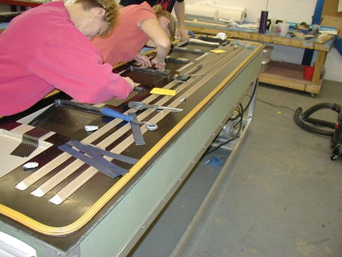
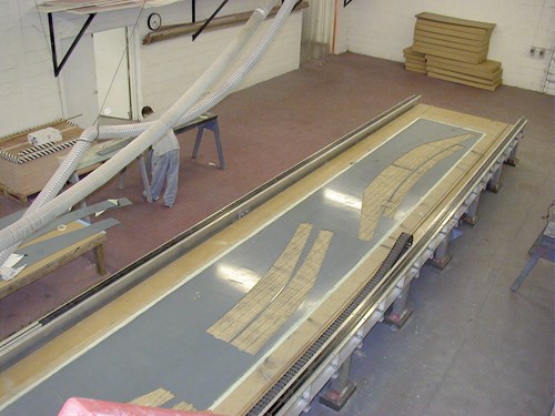
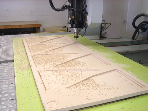
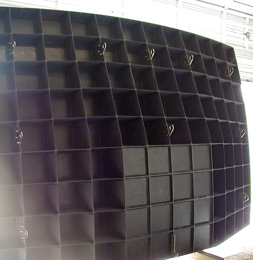
BCT uses a Maxxis 1616 IP/PT 5-axis CNC router (Anderson America Corp., Charlotte, N.C.) and a 42-ft/12.8m 3-axis CNC router to cut the egg-crate lattice sections and serrations from their respective flat-stock panels. The planar egg-crate lattice sections are curved in profile to provide the appropriately shaped support for the parabolic surface. A series of slots are machined into each egg-crate section. The slotted sections can be interlocked, permitting technicians to fit them together in a holding fixture. Each molded face plug is adhesively bonded into its unique egg-crate location, using Gurit’s Spabond 345 epoxy adhesive. Because the assembly’s geometry precludes the use of clamps, pressure is applied to the joints using a proprietary technique. Then, the molded CFRP angle stock is cut to size and adhesively bonded into the egg-crate interstices. Finally, a number of plugs are bonded into a specified area on the backside of the reflector (see Step 8) to provide additional rigidity when the reflector is attached to the kinematic mount, a precision holding fixture commonly used for optics mirrors. This fixture supports and positions the reflector in the compact range test facility.
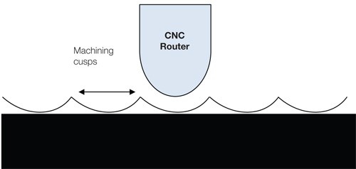
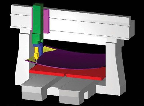
After the face plugs, egg-crate and CFRP angles are bonded, the reflector assembly is stable enough to apply a nominal 1-inch/25-mm thick layer of Gurit T-Paste 70-1 or Axson Technologies (Paris, France) epoxy tooling paste onto the front surface. After a one-day ambient cure and an 18-hour postcure at 170˚F/77˚C, the surface is machined, using precise models and corresponding computer-aided machining (CAM) routines developed during the design process.
A machining pass takes roughly 22 hours and the dish typically requires five passes, each one taking off a smaller amount of material. The final pass, for instance, removes only 0.020 inch/0.508 mm of cured paste.
Here BCT confronted one of the more challenging issues in reflector production: The temperature could not vary more than ±3°F/±1.62°C during surface machining or the epoxy tooling paste would contract due to the difference in CTE between the CFRP substrate and tooling-paste top layer. Given the tight tolerance, even the machining center’s floors and doors became noticeable heat sinks. To ensure temperature uniformity, the BCT team placed thermocouples on the parts, continuously monitoring and maintaining the machining chamber temperature to within tolerance.
While the main structure is processed, the cut-out serrations are loaded back into the routers, where each one’s tooling board surface is CNC-machined to produce its unique parabolic face profile. After machining, hinges are affixed to the serrations, enabling them to be adjusted individually after they are attached to the reflector. Each serration is labeled with its correct position to ensure proper placement during final assembly.
BCT then bolts the constructed reflector onto the kinematic mount on which it will be mounted in the CR facility, with its machined face upright, so it can be scanned using a Faro (Lake Mary, Fla.) Laser Tracker. Next, the entire dish surface is sealed using Awlgrip 545 epoxy primer from Awlgrip North America (Union, N.J.). Using proprietary software, the scan data is transformed into a topographical map. BCT uses the map to identify points on the primed reflector surface that vary outside the 0.0006-inch/0.015-mm RMS tolerance or exceed a peak-to-peak tolerance of 0.001 inch/ 0.0254 mm within a 12-inch/305-mm radius. Low areas get spot sprayed with additional Awlgrip 545 and high points are wet sanded. Then the entire surface is re-scanned. This process is repeated as many as 20 times to ensure that the surface meets the requirements for near optics-level surface quality. Finally, a silver surface coating supplied by E.I. DuPont de Nemours & Co. (Wilmington, Del.) is applied to produce the necessary reflective qualities.
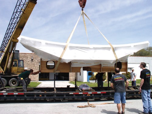
The serrations are processed identically for surface quality, using the Faro laser. Once surface accuracy is confirmed, they are primed, sanded, silvered and fitted with mounting hardware. Then they are packed along with the protectively wrapped reflector in its assembly fixture, ready for transport to the customer, where the reflector will be outfitted with electronics.
CFRP is the key
The CFRP construction and quality-control measures that BCT has developed enable the company to deliver CR reflectors that are one-eighth the weight of a comparable steel dish, yet are significantly stiffer and much more dimensionally stable on the job. Their low weight, in turn, permits the compact range facility operator to use a much less robust support structure and requires a less extensive foundation to stabilize the dish when it is installed at the test facility. These cascading benefits result in an overall compact range solution that is more cost-effective than solutions that rely on reflector dishes constructed conventionally, using steel or aluminum materials.
Related Content
Carbon fiber satellite arm reduces weight, simplifies assembly onto naval vessels
Satcom developer EM Solutions partnered with ACS Australia to replace an aluminum arm design with a 65% lighter, one-piece, corrosion-resistant carbon fiber/epoxy alternative.
Read MoreOrbital Composites wins award from U.S. Space Force to build space factories for antennas
Partners Axiom Space, Northrop Grumman Space Logistics and Southwest Research Institute will help advance ISAM technologies for kilometer-scale LEO antennas, space stations and GEO applications, targeting space factory in 3-5 years.
Read MoreAutomated robotic NDT enhances capabilities for composites
Kineco Kaman Composites India uses a bespoke Fill Accubot ultrasonic testing system to boost inspection efficiency and productivity.
Read MoreComposite molding compound replaces Invar for lightweight small satellite structures
Patz Materials and Technologies and Lawrence Livermore National Laboratory developed a new monolithic optics housing with 80% less weight, near-zero CTE and the high-volume manufacturing required for commercial space.
Read MoreRead Next
All-recycled, needle-punched nonwoven CFRP slashes carbon footprint of Formula 2 seat
Dallara and Tenowo collaborate to produce a race-ready Formula 2 seat using recycled carbon fiber, reducing CO2 emissions by 97.5% compared to virgin materials.
Read MoreDeveloping bonded composite repair for ships, offshore units
Bureau Veritas and industry partners issue guidelines and pave the way for certification via StrengthBond Offshore project.
Read MorePlant tour: Daher Shap’in TechCenter and composites production plant, Saint-Aignan-de-Grandlieu, France
Co-located R&D and production advance OOA thermosets, thermoplastics, welding, recycling and digital technologies for faster processing and certification of lighter, more sustainable composites.
Read More

