Design engineering of tailored preforms
Tailored preforming has opened new doors in composites fabrication, but designing for it requires tools that understand and work with this complex process.
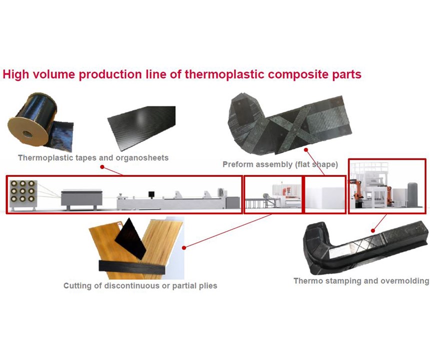
Many new technologies have been developed recently to reduce the cycle time and cost of composites, with the aim of increasing composites’ use in automotive, industrial and consumer goods applications. One of the most promising areas of development is in automated production lines that cut and place thermoplastic prepreg tape to form tailored blanks, and then convert these into parts using compression molding and injection overmolding. Companies active in this development include Airborne (The Hague, Netherlands), Van Wees UD and Crossply Technology (Tilburg, Netherlands) and the French engineering and advanced manufacturing R&T organization Cetim (Nantes, France). The latter unveiled its Quilted Stratum Process (QSP) in 2015. QSP can produce complex-shaped parts with a production line pulse-time of 40-90 seconds. For example, using QSP, an omega-shaped profile molded into an L-shaped beam integrates 13 patches of 1.5-, 2- and 3-millimeter thick organosheet (woven fabric thermoplastic prepreg) and UD tape into a 6-millimeter-thick part with a cycle time of less than 77 seconds per part.
However, to take advantage of automation technology such as QSP, engineers must develop design and optimization methods that can evaluate many theoretical combinations of partial plies and the corresponding variation in the number, thickness, position and composition of plies (for example, reinforcement type and fiber orientation). With this in mind, Cetim has combined its experience in composites structural analysis, nondestructive testing (NDT) and manufacturing with the expertise of ONERA (The French Aerospace Lab) in advanced optimization methods used for years in the aerospace industry. The result is QSD, a tool now available in Altair Engineering’s (Troy, Mich., U.S.) HyperWorks computer-aided engineering (CAE) software. It is basically an optimization add-on that helps to design composite parts made using tape- and organosheet-based processes and to control their cost, including how to reuse production scrap for zero-waste, closed-loop manufacturing.
Four-step process
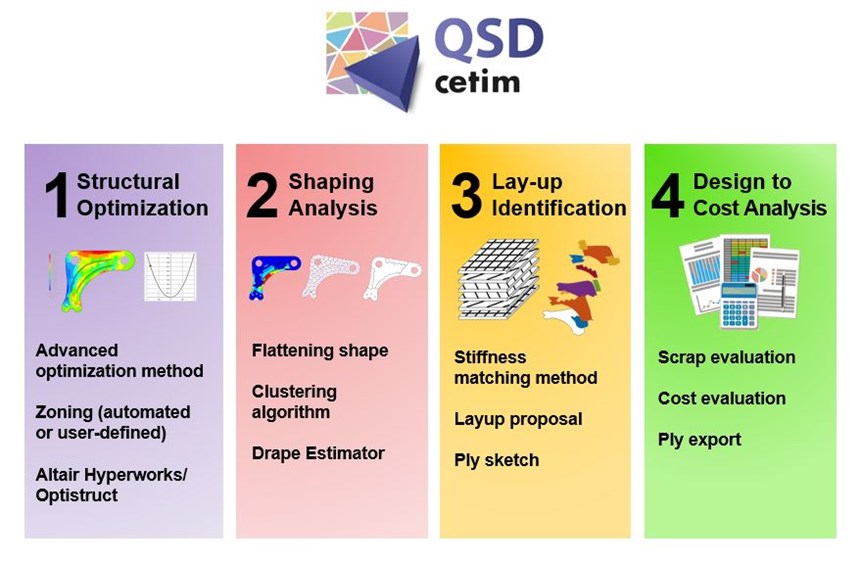
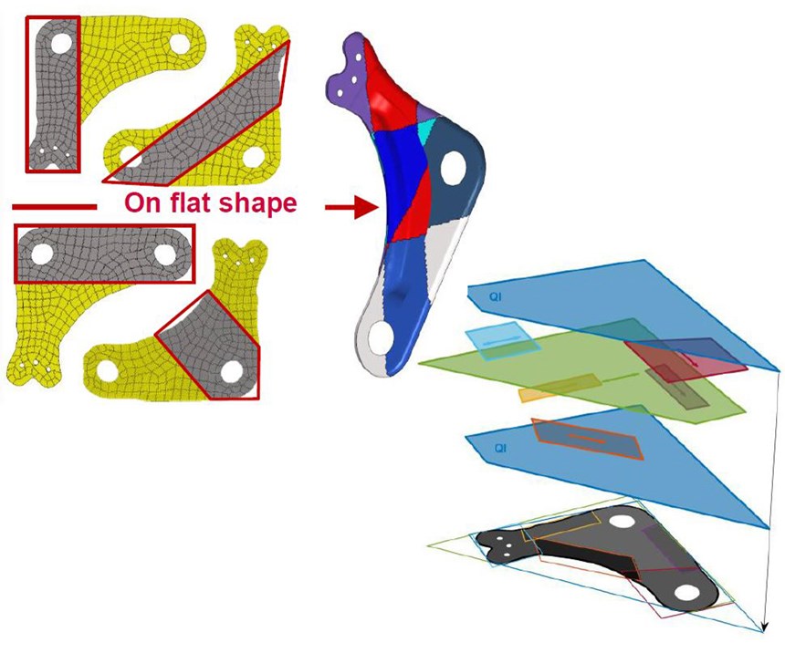
The QSD methodology comprises four steps: structural optimization, shaping analysis, layup identification and design-to-cost analysis (Fig. 1). Each of these helps the designer to quickly test what can be done with the input materials and to make the right decisions regarding mechanical and manufacturing constraints to control part cost. The QSD add-on was developed with Altair to make it directly usable by all HyperWorks OptiStruct users in a well-known environment. These users can take advantage of QSD without developing new finite element models, using their already developed internal know-how with the Altair software.
Structural optimization
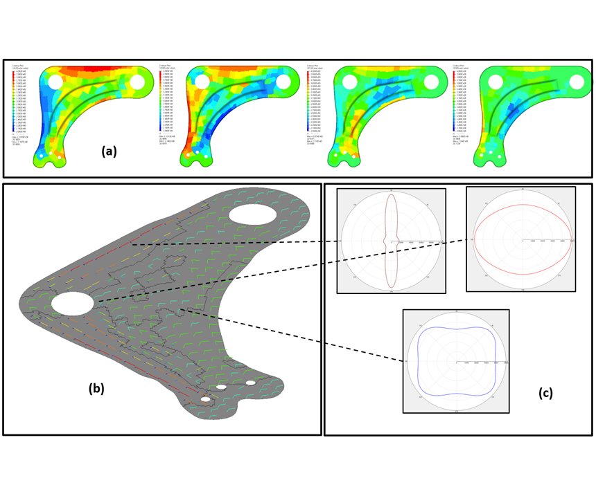
In the first step of QSD’s process, thermoplastic tape materials are selected and their properties — including strength, modulus and other standard parameters — are input from the designer’s selected database or by Altair’s Multiscale Designer database of anisotropic thermoplastic composite materials and their micromechanical models. QSD uses this database and HyperWorks Optistruct to complete a “stiffness matching” optimization. Because some of the results from this analysis are not easily envisioned (for example, anisotropic stiffness), QSD provides a variety of ways to interact with the complex but rich data, including direct variable fields or interpreted results such as the main stiffness directions or a stiffness polar plot (Fig. 1). All of these displays define the same mechanical response, but offer tailored views according to the user-selected preferences. The goal is to help designers understand and visualize the path forward for achieving the desired part performance. This step is where thickness and mass can be optimized, the latter typically reduced by up to 50 percent versus metal parts.
Shaping analysis
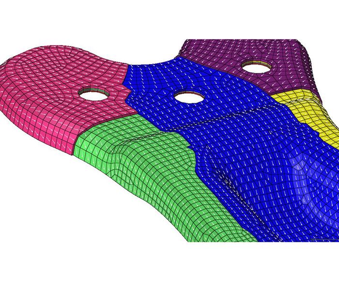
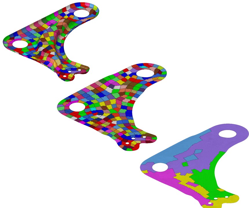
The next step helps designers make essential compromises by first flattening the part — converting from 3D shape to 2D sheet — with the Drape Estimator tool and then performing an automatic partition of this sheet by using a clustering algorithm. The goal is to make evaluation of the link between flat preform and final part simpler and faster. The automotive wishbone shown in Fig. 2 was originally split into 300 zones, based on the finite element mesh and results from OptiStruct, but that number was reduced to five zones by QSD.
The designer can then straighten and smooth the edges of each zone to minimize waste in the corresponding cut plies. This is a key step, improving manufacturing feasibility in order to control cost. This step is also interesting because the designer can evaluate the influence of ply and shape simplification on the part’s mechanical performance. If compromises are to be made between mechanical performance and part manufacturability/scrap/cost, this step provides the data for that evaluation.
Layup identification
The aim in this step is to determine the best local layup for each zone by selecting from a QSD stacking database, or ply library, which can be enriched by user-specific data. The QSD tool helps the designer to sketch the part’s plies and then test to find the best layup strategy by evaluating the part’s response via mechanical criteria (for example, local displacement, buckling factor or eigenfrequency).
Design to cost analysis
In this final step, designers can evaluate the part’s material cost, including scrap waste, and its manufacturing cost due to cutting and assembly of plies. Indeed, the number of plies and the material waste per ply are primary cost drivers. A quick evaluation of waste will soon be available in QSD, enabling estimated values during early design iterations. For final iterations, each ply can be exported to perform a detailed nesting analysis on whatever software the user prefers. Parameters for the part’s cost evaluation formula may also be customized by the designer if needed. Thus, the designer may evaluate various layup strategies and compare their waste, manufacturability, cost and mechanical performance.
Note that QSD enables evaluation of use of all kinds of semi-products such as tape and woven or cross-ply organosheet. It can also evaluate recycled materials, such as nonwoven mats made from recycled carbon fiber by Carbon Conversions, ELG Carbon Fibre and others, or thermoformable sheet made from thermoplastic scraps using Cetim’s Thermosaïc technology or other similar processes. Of course, the mechanical properties of such materials would be needed, but once determined, they could be easily input into the QSD modules, including the final ply library/stacking database. In this way, scrap from this part is used back in this part for zero-waste, closed-loop manufacturing — an ideal goal for all composites manufacturing with regard to sustainability.
Tool for increased use of composites
QSD is suitable for the first steps of the design process because it fits not just with Cetim’s QSP process, but with all processes used to create tailored preforms, regardless of the degree of automation (for example, automated tape placement, automated cutting and hand layup). It is designed to help engineers optimize their parts and avoid bad design choices early in the design workflow.
Reference:
[1] “A novel design method for the fast and cost-effective manufacture of composite parts employing the Quilted Stratum Process” François-Xavier Irisarri, Terence Macquart, Cédric Julien, Denis Espinassou.
About the author
Denis Espinassou is a mechanical engineer and project leader on QSD. He joined Cetim, the French mechanical institute, in 2010 as a specialist of design and optimization of long fiber thermoplastic composite structures. He is also in charge of product development through prototype manufacturing and mechanical validation.
Related Content
Manufacturing the MFFD thermoplastic composite fuselage
Demonstrator’s upper, lower shells and assembly prove materials and new processes for lighter, cheaper and more sustainable high-rate future aircraft.
Read MoreWelding is not bonding
Discussion of the issues in our understanding of thermoplastic composite welded structures and certification of the latest materials and welding technologies for future airframes.
Read MorePlant tour: Sekisui Aerospace, Orange City, Iowa, Renton and Sumner, Wash., U.S.
Veteran composites sites use kaizen and innovation culture to expand thermoplastic serial production, 4.0 digitization and new technology for diversified new markets.
Read MoreThermoplastic composites: Cracking the horizontal body panel nut
Versatile sandwich panel technology solves decades-long exterior automotive challenge.
Read MoreRead Next
Developing bonded composite repair for ships, offshore units
Bureau Veritas and industry partners issue guidelines and pave the way for certification via StrengthBond Offshore project.
Read MoreVIDEO: High-volume processing for fiberglass components
Cannon Ergos, a company specializing in high-ton presses and equipment for composites fabrication and plastics processing, displayed automotive and industrial components at CAMX 2024.
Read More“Structured air” TPS safeguards composite structures
Powered by an 85% air/15% pure polyimide aerogel, Blueshift’s novel material system protects structures during transient thermal events from -200°C to beyond 2400°C for rockets, battery boxes and more.
Read More
