
Direct measurement of laminate through-thickness tensile strength
Although there are indirect methods for determining the through-thickness tensile strength of a solid laminate direct loading can be achieved, using ASTM test methods.
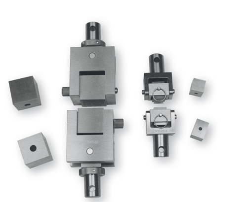
Fig. 1: Comparison of fixture sizes: 50 mm/2 inches (left) and 25 mm/1 inch (right).
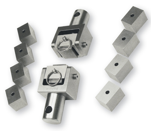
Fig. 3: Typical 25-mm/1-inch fixture with square blocks.

Dr. Donald F. Adams is the president of Wyoming Test Fixtures Inc. (Salt Lake City, Utah). He holds a BS and an MS in mechanical engineering and a Ph.D in theoretical and applied mechanics. Following a total of 12 years with Northrop Aircraft Corp., the Aeronutronic Div. of Ford Motor Co. and the RAND Corp., he joined the University of Wyoming, directing its Composite Materials Research Group for 27 years before retiring from that post in 1999. Dr. Adams continues to write, teach and serve with numerous industry groups, including the test methods committees of ASTM and the Composite Materials Handbook 17.
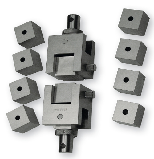
Fig. 2: Typical 50-mm/2-inch fixture with square blocks.
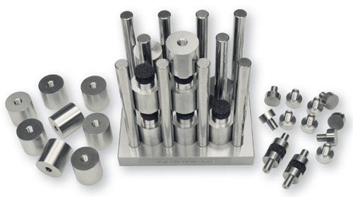
Fig. 4: Specimen bonding fixture (ASTM D 7291-07).


Although there are indirect methods for determining the through-thickness tensile strength of a solid laminate (see “Learn More,” at right), direct loading can be achieved even if the laminate is thin, which is usually the case, by adhesively bonding the faces of the laminate to thicker blocks, typically metal, and then gripping these bonding blocks and applying a tensile force. Because this through-thickness tensile strength is typically low relative to the in-plane strength, it is important to accurately determine it. To do so, it is necessary to minimize stress concentrations induced by nonuniform load distributions on the surfaces of the laminate. These nonuniformities are induced by poor alignment of the end blocks during bonding and/or by misaligned gripping of the end blocks during the tensile test itself.
Two ASTM standards relate to this type of testing. The relatively new standard, ASTM D 7291-07, “Through-Thickness ‘Flatwise’ Tensile Strength and Elastic Modulus of a Fiber-Reinforced Polymer Matrix Composite Material,” was first published in 20071. Previously, a test method first issued in 1952 for measuring the through-thickness tensile strength of sandwich panels, namely, ASTM C 297, “Flatwise Tensile Strength of Sandwich Constructions,”2 became the standard for testing solid laminates.ASTM C 297 defines the basic specimen configuration and loading apparatus that are now specified in both methods. The specimen is either a core material (for example, honeycomb, foam or balsa wood) or a sandwich panel consisting of a core material and facesheets (metal, plastic or composite laminate). Either a square or a round specimen is permitted — no preference is indicated in the standard. Square specimens are used most commonly because they are easier to cut to shape. In theory, and presumably in practice, there are no stress concentrations induced at the corners of a square specimen when it is subjected to through-thickness loading, and thus the selection of a shape becomes arbitrary.


A minimum of 625 mm2 (1.0 in2) of bonding surface area is recommended in ASTM C 297 for continuous bonding surfaces (facesheets, foam or balsa cores). Specimens with discontinuous bonding surfaces — honeycomb cores, for example — might require a larger specimen size to contain a representative number of core cells. In practice, 50-mm/2.0-inch square specimens are commonly used for most types of materials. This specimen size offers a reasonable compromise between sufficiently large test cross section and a desirably compact test fixture. But 25-mm/1.0-inch square specimens as well as both 25-mm/1.0-inch and 50-mm/2.0-inch diameter round specimens also are used, even though the 25-mm/1.0-inch-diameter specimen does not quite meet the 625 mm2/1.0 in2 minimum bonding area recommendation.
Note that a pair of 50-mm/2.0-inch cube-shaped steel bonding blocks already weigh approximately 2 kg/4.5 lb, and a pair of 76-mm/3.0-inch cube-shaped steel bonding blocks weigh approximately 7 kg/15 lb. This is a lot of mass to attach to a relatively fragile specimen and then expect not to induce damage during handling.
Two typical test fixtures are compared in Fig. 1. The fixture on the left accommodates 50-mm/2-inch blocks and that on the right is designed for 25-mm/1.0-inch blocks. Fig. 2 shows in more detail the relatively rugged (but heavy) fixture used with 50-mm/2-inch blocks. (Although square blocks are shown, round blocks can be used in the same fixture.)
Fig. 3 shows a fixture with 25-mm/1-inch blocks — much smaller and lighter than the one in Fig. 2. Since the bond area is only one-fourth as large, the fixture will be subjected to one-fourth the load. It also has a slightly different design than the fixture in Fig. 2. While both have double pivot pins, which provide full articulation, the pivots shown in Fig. 3 are located in the same plane, offering a more classical gimbal motion. This design, however, is not as rugged.
It’s also important to note that with the cubic blocks, four surfaces can be used for bonding, but for round blocks or the elongated (rather than cubic) square blocks in Fig. 3, only two surfaces are available. This difference is significant because the failed specimen has to be removed from the bonding surface and then that surface must be cleaned before its next use. Therefore, use of cubic blocks doubles both the interval between detailed cleaning and the service life of the block.
ASTM D 7291-07’s major contribution is a detailed description of a bonding jig (Fig. 4) designed to maintain alignment of the test specimen with the bonding blocks (called end tabs) during the bonding operation. A maximum of 12 specimens can be bonded in one run. The specimens, and thus the end tabs, are nominally 25 mm/1.0 inch in diameter. The end tabs have a threaded stud for attachment to the testing machine. During the bonding operation, this stud is used to attach the end tab to a bushing of precise (and larger) diameter. After adhesive is applied, the specimen is sandwiched between two end tab/bushing assemblies and lowered into one of the openings between the rods that project upward from the fixture base plate.
After bonding, the bushings are removed and the circumference of the specimen/end tabs assembly is machined adhesive-free. Then the assembly is threaded into suitable holders in the testing machine and pulled in tension. Holder details are not defined in ASTM D 7291.
It remains to be seen whether ASTM D 7291 becomes generally accepted. The bonding fixture is elaborate and expensive, and the suggested post-bonding machining of each specimen is costly as well. Many users, therefore, are likely to continue to follow the much simpler ASTM C 297 standard.
Wyoming Test Fixtures Inc.
References
1ASTM D 7291-07, “Through-Thickness ‘Flatwise’ Tensile Strength and Elastic Modulus of a Fiber-Reinforced Polymer Matrix Composite Material” ASTM International (W. Conshohocken, Pa.), first issued in 2007.
2ASTM C 297-04, “Flatwise Tensile Strength of Sandwich Constructions,” ASTM International (W. Conshohocken, Pa.) first issued in 1952.


Related Content

Crashworthiness testing of composites: A building block approach, Part 2
Following the previously discussed coupon-level testing element, subcomponent and component testing are the next steps in designing crashworthy composite structures.
Read More
Multi-scale 3D CT imaging enables digital twinning, high-fidelity simulation of composite structures
Computed tomography (CT) provides highly accurate 3D analysis of internal microstructure, performance simulation of carbon fiber/PEEK satellite strut.
Read More
Photothermal tomography for locating, quantifying defects in composites
Years of infrared testing development result in thermography technology that is no longer just qualitative, but can define defect size and depth, making additional UT scans obsolete.
Read More
Interlaminar tensile testing of composites: An update
New test method developments for measuring interlaminar tensile strength address difficulties associated with the ASTM D6415 curved beam flexure and ASTM D7291 flatwise tensile tests.
Read MoreRead Next

Through-the-thickenss tensile strength testing using a curved beam
The in-plane strength properties of a composite material, axial and transverse tension and compression and in-plane shear, are usually the first to be considered in design. However, through-the-thickness (interlaminar) strength properties cannot be ignored. Through-the-thickness tensile strength, in particular, can be critical to structural performance.
Read More
Developing bonded composite repair for ships, offshore units
Bureau Veritas and industry partners issue guidelines and pave the way for certification via StrengthBond Offshore project.
Read More
VIDEO: High-volume processing for fiberglass components
Cannon Ergos, a company specializing in high-ton presses and equipment for composites fabrication and plastics processing, displayed automotive and industrial components at CAMX 2024.
Read More