Lattices often crop up in nature. Take the conspicuous design of dragonfly wings (left), a spider web (middle) or the veined underbelly of a Victoria Amazonica water lily (right). Photo Credit: Getty Images (left, middle) and Pixaby (right)
Part 1 of this series investigated the considerable challenges the composites industry — and manufacturing as a whole — still face when designing biomimetic products, and some ways in which industry is overcoming or exploring these obstacles. Biomimicry is an industrial product philosophy that uses inspiration found in nature to solve complex human design challenges. It is studied across a variety of fields and is used to inform more sustainable material, process and system practices. Success, however, relies on the ability to align man-made design and manufacturing processes with those we see in nature.
In Part 2, CW takes a step away from the materials aspect of biomimetic design and looks a little closer at current composites manufacturing processes that have the potential to make bio-inspired structures a reality, from shaping freedom to bionic systems.
3D printing lattices
“When we go into nature and look into more complex load cases we start finding lattices,” Fedor Antonov, CEO, Anisoprint (Luxembourg), says. “A lattice is a set of ribs, and each rib is a 1D object. If it’s 1D, then that means that it exhibits a very simple, 1D stress-strain state — compression or tension.” In anisogrid lattices, for example, the focus of the material properties are right along those ribs (i.e., in the fiber direction). Fiber density and directionality can also be affected by adjusting angles or adding more ribs in one or more directions, enabling maximization of material properties and directional distributions while simultaneously improving weight efficiency.
Anisoprint is a hardware startup producing continuous carbon fiber 3D printers that cut costs and increase productivity. The company also specializes in 3D printing of anisogrid lattice structures that consist of dense systems of unidirectional (UD) composite helical, circumferential and axial ribs, exemplifying Anisoprint’s own inclusion of nature through the lens of traditional fiber-reinforced composites.
These anisotropic lattices have found footholds in broadcasting towers, aircraft fuselage structures and spacecraft, and they continue to do so because they effectively distribute loads. They are not, however, typically found in nature. Lattices that are commonly found in nature, like the zigzag pattern of a spider web (called stabilimenta), or the cellular, hollow branching tubes of dragonfly wings — composed of rectangular frames along the leading edge and hexagons along the trailing surface — are shaped in response to environmental factors. And while many of these natural lattice-like structures are able to provide very efficient load distribution, Antonov says, they cannot yet be obtained by conventional composites technologies like filament winding, fiber placement or pin winding.
It should be noted that lattices have been developed via these processes. However, the processes themselves still have limits, which affect the level of lattice complexity they can produce. Filament wet winding is rarely used, because, in addition to being inefficient and expensive via the use of silicone molds covering the mandrel, it can only create geodesic (straight) reinforcement paths; comparatively, irregular grid density and non-geodesic reinforcement typically provides a more efficient load distribution for a lattice structure. Unconstrained fiber placement, like automated fiber placement (AFP) or automated tape laying (ATL), are also limited because of small rib heights (through the use of flat tapes) and thick intersections — although the latter is being addressed via new place and cut strategies (see “Integrating antennas into composite aerostructures”). Finally, pin winding — wet fiber robotically wound around a mold with designated pins — while useful for placing fibers under tension, lacks transverse fiber consolidation, resulting in gaps and pores in the fiber tows of the ribs, as well as reduced buckling force.
Antonov believes the approach to this challenge is not to “copy” nature — which returns to our earlier conversation in Part 1 about emulation — but rather to develop components that look natural. “I don’t know how to play a violin by listening to a top performer,” he says, using the analogy to refer to nature’s principles. “We just copy [nature] but we don’t understand why. Sometimes nature gives some results, but we need to understand the basic principles to really be able to perform on the same level. What really makes sense is if we develop design approaches or methods [for composites] that can help us to create structures that look natural based on similar rules and principles. It’s not really biomimicry, but it is very good evidence of the fact that we are going the right way [to understand natural structures].”
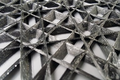
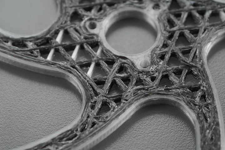
Compared to other composites manufacturing processes, Anisoprinting makes in-situ composite lattices possible without doubling the fiber-volume fraction (FVF) at junctions. At top is an up-close view of one such lattice component. The bottom image depicts the complex, non-geodesic shape of an impeller part. Photo Credit: Anisoprint
Topology optimization and generative design for anisotropic materials, he says, is one way to produce natural-looking structures. “The structures you create [using topology optimization and generative design] look much more natural [than typical, man-made structures],” he notes, “because in the end, it’s all the optimization algorithms. Evolution itself is an optimization algorithm.” Nature, in its own way, is more complex because of its adaptive designs, which are often a direct result of millions of years of evolution and environmental changes. This is different from design for manufacturing, which can only be simulated based on environmental expectations. However, “Generative design algorithms are, I think, one of the biggest breakthroughs because we [humans] are limited in, let’s say, our vocabulary,” Antonov continues. “We cannot measure too many different dimensions. Now we delegate to computers, and they can actually create complex shapes which nature creates.”
Anisoprint currently focuses on hardware, materials and software. 3D printing — specifically, composite fiber co-extrusion (CFC) — falls into this realm of design optimization and is one key technology Anisoprint incorporates to manufacture lattices. This is primarily because of the technology’s control of in-situ fiber laying, flexible fiber-volume ratios and separate control of plastic and fiber flow through two input nozzles, ensuring a smooth intersection point at lattice junctions without an intersection increase.
“At the intersection points of a lattice grid, your fiber volume fraction [FVF] doubles because the fiber has to continuously go through that intersection. So you need to have some sort of control in order to avoid thickness deviations in the intersection,” Antonov says. “It’s extremely important for these kinds of structures [composite lattices] to be straight because of the stress-strain state of each rib. But if you have this bump in the middle, then your fiber is not straight anymore, and the load is now no longer in parallel with the fiber but locally at the angle. Then the stress-strain state becomes very complex and fails on the spot.”
Weak consolidation in 3D printing, he notes, means that the FVF using that process will not be higher than 40% for the lattice ribs but it will be doubled along the intersections (70-75% at the highest). In this respect, whereas there is typically a tradeoff between high mechanical properties (high FVF) or high structural properties (shape and material) when it comes to consolidation, lattices can arguably offer the best of both these worlds.
Bionics and the automated processing landscape
There is an important difference between biomimicry and bionics. While the former has been defined to emulate biological structures to produce a final product, the latter focuses solely on the design and application of engineering systems and modern technology that implements functions that perform like living organisms or parts of living organisms. Bionics is a very familiar concept in computer sciences, like artificial intelligence (AI), evolutionary computation and robotic design.
Professor Axel Spickenheuer, head of the complex structures group in the Composites Department at Leibniz Institute of Polymer Research (IPF, Dresden, Germany), cites tailored fiber placement (TFP), a process CW reported on in 2013, as falling under the bionics category — more so than under biomimicry. TFP adapts complex, topology-optimized shapes using mathematical algorithms. “TFP can still help inform creating complex bio-inspired shapes,” he says, “but the question is how do you generate them?”
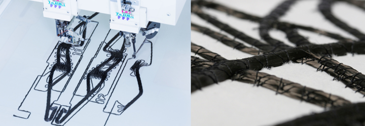
Tailored fiber placement (TFP) enables the production of complex, often curvilinear composite lamina with locally adjusted thicknesses and fiber orientations, like the topology-optimized CFRP brake booster preform (right). Photo Credit: Composites Department at Leibniz Institute of Polymer Research (IPF)
The embroidery-based preforming process, often described as filling a gap between AM and AFP, was invented at the IPF in 1992 and originally sprang from a desire to mimic lightweight structures in nature. Called “fiber printing” by its advocates, TFP begins with a flat textile substrate, or, for a thermoplastic composite, a matrix-compatible foil material. Continuous tows or rovings are affixed to the substrate using a double-locked stitch in a zigzag pattern deposited by a purpose-built stitching machine. Multiple stitching heads can perform 1,000 zigzag stitches per minute per head at a speed of 5 meters per minute. Resulting dry fiber preforms can be processed using either resin transfer molding (RTM) or vacuum bag resin infusion. Thermoplastic preforms can be stamp-formed and also overmolded.
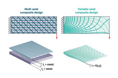
TFP’s strengths lay in its ability to manufacture multiaxial reinforcements of many plies, with variable thicknesses, as well as precise and complex fiber architectures in almost any orientation with reduced material waste. Because of this degree of design freedom, fiber patterns can be produced to meet practically any load path, including curvilinear shapes. In fact, it is best suited for manufacturing variable-axial — also known as variable-stiffness and variable angle-tow — composites, which can be defined by principal stress (PS) criterion.
“What you want as a composites engineer is for the fibers to be aligned in the highest stress region and the highest stress direction,” Spickenheuer explains. “One thing we discovered was that former design approaches like computer-aided internal optimization [CAIO] don’t consider typical features of curvilinear-placed laminates, e.g., a varying thickness distribution which could be found on finally produced TFP parts. What we are pointing out nowadays as the motivation for variable-axial composites is that we have this non-constant hybrid orientation where fibers diverge and with that, thickness is increasing or decreasing. This was something we had to take into account for the numerical modeling of such structures.”
The “biological” aspect of TFP came about when similarities were found between PS design and the design of a tree’s fibrous material used to reinforce itself, Spickenheuer notes. Nevertheless, while PS design — and thus this biological aspect — remains the foundation of TFP manufacture, IPF has phased out of a “pure principal of biomimicry and developed our own realm of mathematic design principals through formulations, numbers and algorithms.”
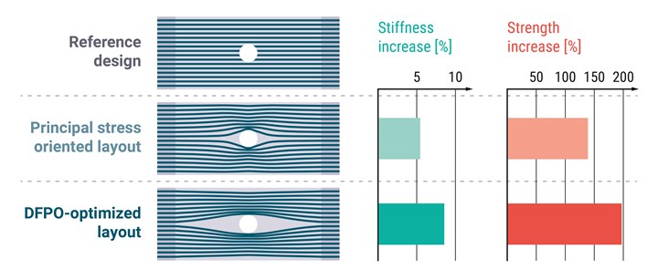
Direct fiber path optimization (DFPO), performed on an open-hole anisotropic variable-axis composite specimen, resulted in a dramatic increase in strength of about 200% compared to the UD specimen, and a significant improvement compared to a principal stress (PS) specimen. Photo Credit: Composites Department at Leibniz Institute of Polymer Research (IPF)
He emphasizes one novel optimization methodology, direct fiber path optimization (DFPO), which was performed on an open-hole specimen — a carbon fiber TFP layer stacked on top of a +45° woven fabric layer. “What we do now is get an initial design of the trajectories and then make the calculation. With our modeling approach, we model the stiffness distribution and fiber orientation and make the stress analysis of that part. Then we have an optimization algorithm to determine a peak value for a preferable stiffness — so how much a part is deforming — and then we try to bend the fibers in a way that fulfills this.” Direct fiber path optimization, performed on an open-hole anisotropic variable-axis composite specimen, resulted in a nearly 10% increase in stiffness and up to 200% in strength compared to the unidirectional (UD) specimen and a nearly 42% increase in strength compared to the PS specimen. “This interesting outcome you wouldn’t have come to intuitively,” he says, “but through the algorithm, it makes total sense.”
Braiding textiles
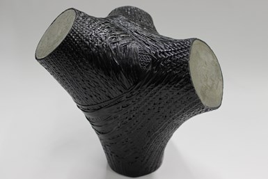
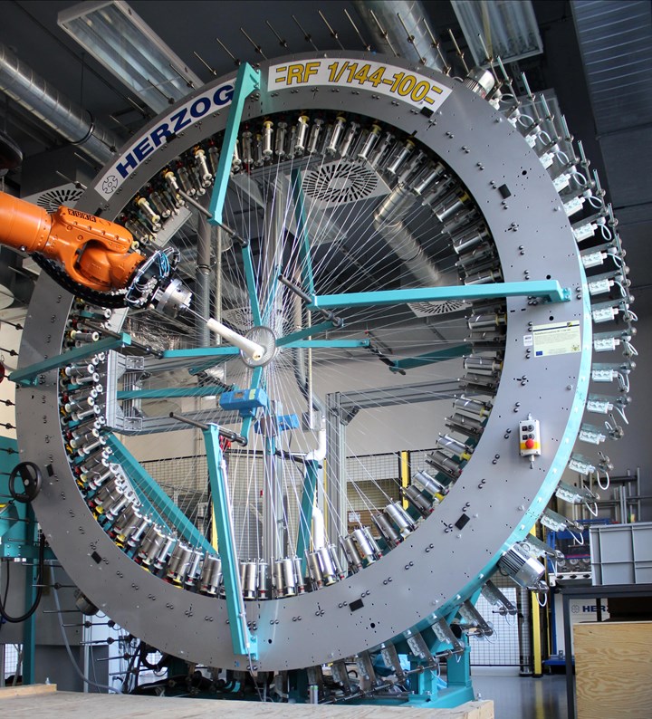
The concept of bionics is also reflected in other automated systems for composites manufacture. Braiding, for example, is a textile fabrication method that has seen use in bio-inspired structures. An interdisciplinary research team from the University of Stuttgart (ITKE, ICD and ITFT) and the German Institutes of Textile and Fiber Research (DITF, Denkendorf) analyzed the plant-branching effect and developed a spatially branched, braided, carbon fiber-reinforced, high load-bearing supporting node. In this project, high-strength carbon fibers, used in synergy with concrete, were precisely aligned and arranged to maximize their mechanical properties. A radial braiding machine was able to simultaneously braid up to 216 threads to produce a 3D textile preform with three fiber directions, which was then impregnated with a thermosetting polymer and consolidated into the solid fiber-reinforced polymer (FRP) “hull,” which the researchers termed the braided fiber composite. This “hull” was then filled with concrete. According to researchers, the concrete transferred the compressive forces that occurred, while the outer FRP hull absorbed the tensile or bending stresses of the load-bearing nodes.
To make this possible, the team developed a planning tool using software based on a Rhino/Grasshopper environment. It can define the mandrel path through the braiding machine in a virtual braiding environment location — determining all collision possibilities of the robot in one step and generating the control code for the six-axis robot (responsible for pushing/guiding the mandrel through the center of the braiding machine) and braiding machine directly in another — reducing setup time.
Robotic filament winding in architecture
Just as important, automated fiber winding of composites has found its place among students and researchers at the University of Stuttgart (Germany). Led by Professor Achim Menges, head of the Institute of Computational Design (ICD) and Professor Jan Knippers, head of the Institute of Building Structures and Structural Design (ITKE), an annual pavilion series has looked at the architectural transfer of biological principles by means of computational design, simulation and digital fabrication technologies, alongside fiber-reinforced composites — because nature also uses fibrous composites, Menges notes.
The uniquely shaped pavilion structures resulting from this work feature optimized load transfer and were made without the need of molds, thanks to the university’s robotic filament winding technology. This automated system is run by software developed by the Stuttgart teams for more intelligent and tailored movement, specifically orienting and using only the quantity of fibers necessary for optimal load transfer.
These pavilions are a first step in applying biology-based composites concepts to construction and architecture. “The requirements modern buildings have to fulfill today are very complex, often contradictory, and during their life cycle need to be adapted for utilization, economical and ecological reasons,” notes Knippers in a co-authored paper, “Design and construction principles in nature and architecture.” He continues, “In the last decades, emerging ecological demands have been a driving force in the development of highly evolved building technologies, including material development and automation.”
These pavilions have attracted industry attention over the years. The ICD/ITKE Research Pavilion 2016/17, for example, is a 12-meter-long cantilevered structure that, like all of the pavilions, builds on the university's investigation of integrative computational design, engineering and fabrication, and explores the pavilion’s spatial ramifications and construction possibilities. The structure is made from more than 180 kilometers of woven resin-impregnated glass and carbon fiber to mimic silk hammocks spun by moth larvae. To create the long-span shape, the team combined two stationary industrial robots with long-range drones to wind the fibers, with the drones serving as a “transportation system to pass the fiber from one side [of the structure] to the other.” Moreover, using an integrated sensor system, the robots and drone were able to adapt fiber-tension levels based on process conditions.
Numerous other “bio-inspired” structures have been built , some likened to organisms such as elytra (a beetle’s forewings) and sea urchins.
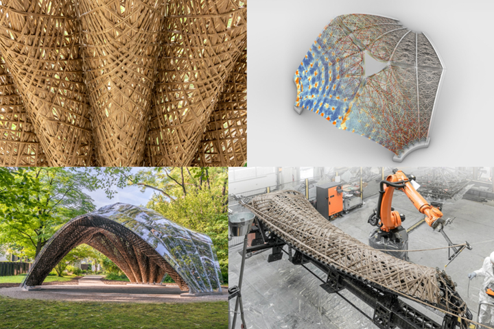
More recently, the livMatS Pavilion, located in the Botanical Garden of the University of Freiburg (Germany), represents Menges’ and Knipper’s transition to robotically wound natural flax fibers for more viable, resource-efficient and sustainable structure construction on a larger scale, taking inspiration from the net-like wooden structures of the saguaro cactus (Carnegia gigantea) and the prickly pear cactus (Opuntia sp.). According to the ICD’s website, the 45-square-meter pavilion stems from the successful collaboration of an interdisciplinary team of architects and engineers of the ITECH master’s program at the Cluster of Excellence “Integrative Computational Design and Construction for Architecture (IntCDC)” at the University of Stuttgart and biologists from the Cluster of Excellence “Living, Adaptive and Energy-autonomous Material Systems (livMatS)” at the University of Freiburg.
After validation of a first series of natural fiber prototypes, production data was generated and passed on to project industrial partner, FibR GmbH, for the structure’s robotic fabrication. The final, 1.5-ton livMatS Pavilion is comprised of 15 continuously spun flax fiber components, as well as a fibrous capstone element topping off the structure. Photo Credit: ICD/ITKE/IntCDC University of Stuttgart
The coreless filament winding process used for the livMatS Pavilion is detailed in an article, “Robotic building with natural fibres” by Dr. Ruth Menßen-Franz from Biopro Baden-Württemberg GmbH (Stuttgart, Germany). The innovative use of flax fibers required some changes in the winding process — for example, compared to endless-drawn synthetic fibers, a natural fiber roving is said to consist of several individual short pieces arranged in parallel. “So that they are not pulled apart during processing and to prevent the roving from tearing, the tensile forces have to be adjusted and a braided cord has to be incorporated for stability,” Menßen-Franz notes in the article. “Before the rovings are wound onto the shaping frame, they are run through a bath of epoxy resin; after curing in the oven, the wound elements are then highly stable.” The pavilion is also covered with a waterproof polycarbonate skin to protect the fibers from direct UV light and moisture.
By its very nature, the pavilion is said to represent the opportunities bio-inspiration has to offer, for architecture and other areas of development. Ultimately, Menges claims that developments in digital design and robotic construction will transform the field of engineering. “I think we’re experiencing another paradigm shift, a fourth industrial revolution,” he tells Dezeen.
But in what ways is this shift in digital design and automated manufacturing happening? According to Nathan Hays, a biomimicry and architecture graduate in the early stages of launching nuLUCA, a biomimetic design consulting and education firm, “the obvious changes come to mind: More sophisticated designs can be realized with less capital and in less time; prototyping, experimentation and innovation is accelerated (and increasingly democratized). Modeling tools are becoming more powerful computationally while also becoming more accessible, and architects and designers are becoming more fluent in generative design languages.”
Where biomimicry is headed
So what’s next in the study of biomimetic composites? “Next is copying [nature’s] functions, such as the sensing, the healing, the adaptability and the repairing,” Masania says, referring to animate materials as another evolving topic that aims to better understand natural materials and their functions. “What we’ve [the Shaping Matter Lab] been doing [up until now] is a ‘brute-force approach’ to structural materials.” By understanding and controlling organisms, composite structures could potentially be “programmed” in the way they grow, rather than machining or modifying the final object. This could also avoid the chemical steps typically associated with producing materials and harness the living responsive power of biological matter, Masania notes.
Along this same avenue, some of Richard Trask’s work at the University of Bristol’s (U.K.) Department of Aerospace Engineering has involved plantae-inspired vascular networks within fiber-reinforced polymer (FRP) laminates for self-healing structures. The goal of the network is to sense structural damage before initiating a triggered healing response. Another step, per a project with an undisclosed helicopter manufacturer, is to apply thermal heat management, in addition to the self-healing stimuli.
Another area of growing interest, says Trask, is 4D materials, active smart materials that can be stimulated by temperature, dehydration, chemicals, humidity and other physical properties to impart some movement over time.
In terms of bionic systems, Spickenheuer believes bringing together topology optimization and parametric design — a method of shaping features according to algorithmic processes — for fiber orientation is going to be the key focus in the next few years. Together, the two methods address material layout optimization and structural shape (i.e., building elements and engineering components) design per input constraints and parameters, thus potentially leading to a closed optimization process. “We have already been doing some publications, working on some projects with companies such as Toyota Central Research and Development Lab, and Kyoto University,” he notes.
But at the very heart of the biomimetic methodology is designing for efficiency and sustainability — such as using material only where it’s needed for minimized waste, or even considering more natural materials for a product’s end of life. “One of the biggest advantages is that with biomimicry, efficiency and sustainability go hand in hand,” Nummy says. “As we become more focused as a society on sustainability, the idea of having design solutions that are both efficient and sustainable is going to be really appealing to those design challenges. We have to bring sustainability to the forefront of the design process and start to shift our thinking away from maximizing design, toward optimizing design.”
Related Content
Bio-based acrylonitrile for carbon fiber manufacture
The quest for a sustainable source of acrylonitrile for carbon fiber manufacture has made the leap from the lab to the market.
Read MoreCombining multifunctional thermoplastic composites, additive manufacturing for next-gen airframe structures
The DOMMINIO project combines AFP with 3D printed gyroid cores, embedded SHM sensors and smart materials for induction-driven disassembly of parts at end of life.
Read MoreTU Munich develops cuboidal conformable tanks using carbon fiber composites for increased hydrogen storage
Flat tank enabling standard platform for BEV and FCEV uses thermoplastic and thermoset composites, overwrapped skeleton design in pursuit of 25% more H2 storage.
Read MoreSulapac introduces Sulapac Flow 1.7 to replace PLA, ABS and PP in FDM, FGF
Available as filament and granules for extrusion, new wood composite matches properties yet is compostable, eliminates microplastics and reduces carbon footprint.
Read MoreRead Next
Helicoid Industries releases three use cases of Helicoid technology
Use case applications with Helicoid technology implementation demonstrated mechanical performance improvements, such as impact resistance and strength.
Read MoreDrawing design cues from nature: Designing for biomimetic composites, Part 1
Biomimicry is an interdisciplinary methodology that can inform composites design and manufacturing via use of more effective and sustainable materials, structural fabrication and technological practices.
Read MoreVIDEO: High-volume processing for fiberglass components
Cannon Ergos, a company specializing in high-ton presses and equipment for composites fabrication and plastics processing, displayed automotive and industrial components at CAMX 2024.
Read More


