Fraunhofer ICT in-mold pressure sensors for HP-RTM
Pressure sensor-based mold fill expected to maximize part consistency and minimize cycle time for auto industry molders.
Researchers in Germany are investigating the use of in-mold pressure sensors to control mold filling in high-pressure resin transfer molding (HP-RTM). The goal is a potential new means of improving part-to-part consistency and decreasing cycle time — improvements that could lead to long-sought, mid- to high-volume automotive part production. The research team in the Department of Polymer Engineering, based at the Fraunhofer Institute for Chemical Technology (ICT, Pfinztal, Germany), is working closely with a variety of partners, from among materials and machinery suppliers as well as automotive OEMs. Recently, the team completed a study investigating the use of a new pressure-controlled HP-RTM process (PC-RTM) process, applied to two well-known process variants, high-pressure injection RTM (HP-IRTM) and high-pressure compression RTM (HP-CRTM).
The study in context
In “standard” RTM, relatively low pressures (1 to 20 bar) are used to impregnate the fabric, but HP-RTM uses pressures up to 150 bar during the mixing and dosing of the resin and hardener in the mixing head, and applies mold cavity pressures of up to 120 bar during injection/compression. Project researcher and Ph.D. candidate Philipp Rosenberg says one of the shortcomings of low-pressure RTM is that its pump system, by design, produces limited injection pressure.
“Because of the limited injection pressure, as the resin impregnates the preform,” Rosenberg explains, “flow rate is limited, which leads to long injection time.” In HP-RTM, however, high-pressure mixing and dosing equipment produces high injection pressure. In standard HP-RTM the injection is carried out under full clamping force, resulting in a high cavity pressure and, thanks to the high-pressure injection systems, a constant, high resin flow rate with no fall-off guarantees short injection and allows for a faster gel time in the resin, emitting a faster cure time as well.
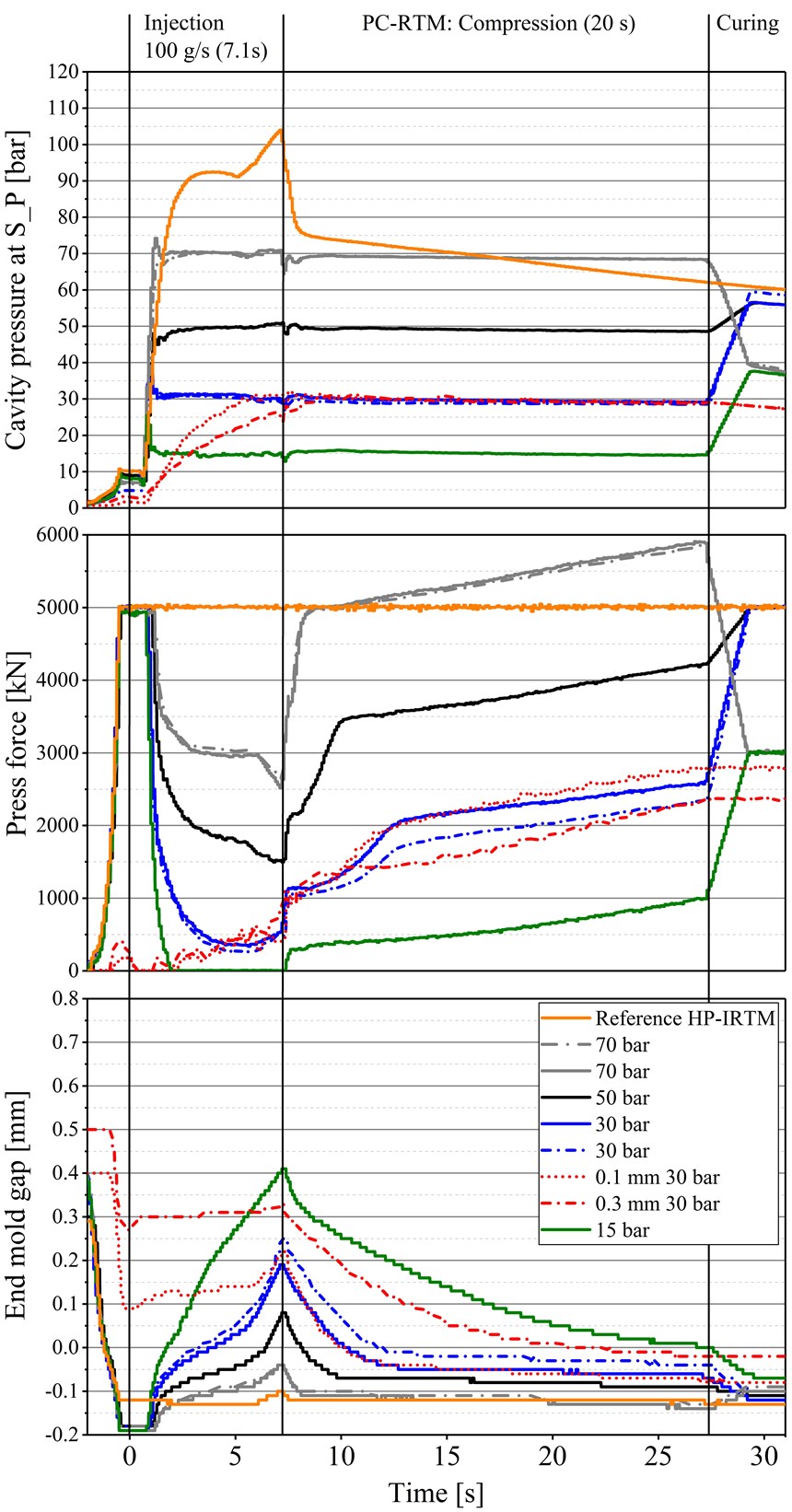
As with standard injection molding, the pressure sensors in this study were used to monitor the rate of cavity pressure increase up to a peak, or pre-set value. This study used a novel technique to allow a pressure sensor to control the width of a slight and variable opening or gap in the mold closure. This “end-mold gap,” as well as varying press clamping force, would be used cooperatively as a means of controlling cavity pressure during the injection and compression steps. “The big disadvantage in decreasing flow rate to reduce the in-mold pressure increase during injection is you lose time, which we want to avoid,” says Rosenberg, emphasizing that that can be avoided with ICT’s method, “Our goal is to actively control in-mold pressure, not just decrease it for a certain time.
HP-RTM cycle time: The challenges
Rosenberg and colleagues Dr.-Ing Bernd Thoma and Prof. Dr.-.Ing Frank Henning, conducted the study using a Dieffenbacher Compress Plus DCP-G 3600/3200, equipped with an RTM 8/3.2 K RTM resin dosing/injection unit with a self-cleaning head capable of mixing, dosing and injecting directly into the cavity. The dosing/injection unit is supplied by KraussMaffei Technologies GmbH (Munich, Germany). The maximum press force for this study was 600 tons (6,000 kN). “The basic goal is to achieve full part consolidation using only as much pressure as required, and pressure transducers can make that possible if they are used to actively control the process,” says Rosenberg.
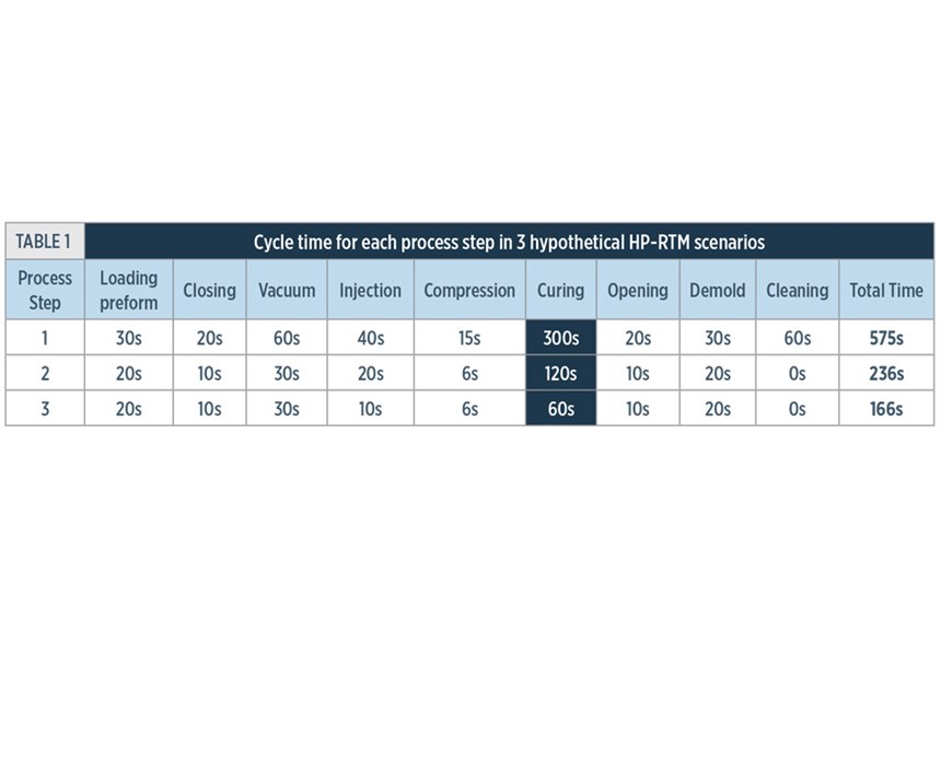
That goal, simple in theory, is more difficult to achieve in practice; indeed, the research, and the problem(s) it is attempting to solve, are directly related to some of the challenges inherent in achieving the low cycle times required in a commercial, high-volume production facility using the HP-RTM process. Producing 50,000-80,000 parts per line per year requires a cycle time of 3 minutes or less. Table 1 summarizes the results of a cycle time analysis conducted by the research team for a typical HP-RTM process. The process comprises nine stages: loading the preform, closing the mold, vacuum step, resin injection, compression, curing, mold opening, part demolding and mold cleaning. The portion of the cycle time allotted to each step is listed under three scenarios: resins with 5-, 2- and 1-minute cure times (step 6).
Assuming other process optimizations in addition to faster cure (e.g., decreases in the time to load the preform, close the mold, draw a vacuum, etc.) only scenario 3, with a 1-minute cure, 10-second injection and 6-second compression time was able clock in under the cycle-time threshold for high-volume production at 166 sec (2.8 min).
And therein lies the difficulty: Although there are now available “snap-cure” resins that offer short gel and cure times of 2 minutes and less, these resins require high flow rates to inject the resin as quickly as possible. The industry also demands more integrated components that require less post-mold assembly, but requires that these complex parts be injected and infiltrated quickly to meet yearly high production goals. HP-RTM equipment is fully capable of applying the necessary pressure to make this happen: Upon injection, with the mold closed and full press force applied, cavity pressure can increase quite rapidly (>100 bar). But that capability carries with it three risks:
- First, this rapid pressure increase can result in back pressure as the fiber reinforcement creates resistance to resin flow impregnating it. The back pressure can be compounded by preforms with complex, 3D geometries. In the worst case, the counter pressure can exceed the injection pump’s capacity and shut down the flow.
- Second, high pressure and a high flow rate of resin can cause fiber displacement. In situations where fiber orientation is critical, fibers could be washed out of position, and the performance of the finished part could be compromised.
- Third, if a lightweight, low-density core is co-molded with the preform, pressures that are too high can crush the core. Again, the part is compromised.
This, in short, is the quandary: Pressure too great can result in an aborted run, but pressure reductions to avoid that risk result in cycle time elongation. The task then is to learn how best to apply and use pressure-sensor technology, offering molders a potential means to find and maintain the pressure “sweet spot” that optimizes product quality and cycle time.
Initial pressure-sensor trials
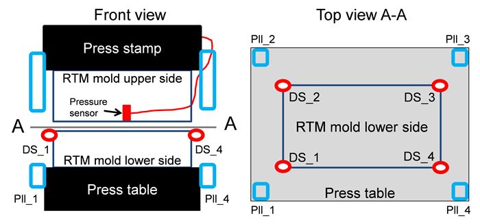
In search of that sweet spot, Rosenberg’s research group assembled specialized equipment. In addition to the aforementioned hydraulic press and injection unit, the study required four capacitive distance sensors (type CS5) from Micro-Epsilon Messtechnik GMbH & Co. KG (Ortenburg, Germany) installed at the mold’s edges (Fig. 1), which enabled precise measurement and control of the mold end gap.
Additionally, nine 6167A pressure sensors supplied by Kistler Instruments AG (Winterthur, Switzerland) were installed in the upper half of the 900-by-500-mm2 mold cavity. Total mold cavity height was 2.2 mm. The data of three of the sensors (S1-S3) were used to monitor the in-mold pressure in this study; additionally, in the pressure-controlled trials, sensor S_P, positioned near the injection film runner , was connected to the hydraulic control unit of the press and used to control cavity pressure by variable mold gap and press force. Dow’s VORAFORCE 5300 fast-cure epoxy resin was used to infuse a 1210 g/m2, E-glass unidirectional fabric manufactured by SAERTEX GmbH & Co. KG (Saerbeck, Germany). (The researchers verified the process works with carbon fiber but primarily used glass fiber to reduce costs.)
As detailed in a paper presented at the 2016 SPE Automotive Composites Conference and Exhibition (SPE ACCE), Rosenberg, along with colleagues B. Thoma and Frank Henning, then ran a series of non-pressure controlled, preliminary high-pressure injection reference trials at a constant press force of 5000 kN and different injection rates: 100, 80, 60, 40 and 20 g/sec. Cavity pressure was recorded using the S3 sensor positioned 25 mm from the injection gate.
The trials established the linear dependency of cavity pressure increase with volumetric filling of the cavity, with a maximum pressure of more than 100 bar for four of the five highest flow rates, leading to slight opening of the mold (overmolding) and a subsequent, approximately 20-bar drop in cavity pressure. These reference trials demonstrated that maximum cavity pressure can be controlled only to a limited degree by varying flow rates, producing longer injection times.
In the pressure-controlled (PC-RTM) trials that followed, the researchers studied the ability of a pressure sensor connected to the hydraulic press control unit to control cavity pressure in two scenarios involving the application of a variable mold end gap to two common variations on RTM:
- A press-force-controlled variant, roughly equivalent to HP-IRTM, with a constant, initial press force and a pressure sensor signal acting as input for controlling press force during injection and compression. After reaching a pre-defined pressure during injection, the sensor signals the hydraulic unit, thus decreasing press force and allowing the mold to open slightly and maintain the preset cavity pressure. Controlling cavity pressure in this mode is made feasible by press design, specifically four parallel holding cylinders that exert force against the main cylinder, thereby keeping the platen parallel, and ensuring consistent part thickness.
- A variant with a pre-defined, initial end mold gap and active in-mold pressure control and variable (zero) press force upon injection – i.e., the HP-CRTM method. This process generates lower cavity pressure upon injection because of the higher porosity/permeability of the preform. When the preset pressure is reached, the end mold gap opens to keep it constant. The same mechanism (sensor/end gap) is used to control cavity pressure during compression, which achieves final part thickness. For this study, end mold gaps of 0.1 and 0.3 mm were used.
The flow rate for the trials involving both variants was 100 g/sec. The trials for variant #1 were run at pre-selected pressures of 70 bar, 50 bar, 30 bar and 15 bar. The pre-set pressure limit for variant #2, with initial end-mold gap positioning of the mold, was 30 bar.
For the press-force controlled variant runs (#1), the rate of pressure increase, with an initial press force of 5,000 kN, was similar to the 100-g/sec reference trial with no pressure control. Total injection time was about 7.1 sec., and maximum cavity pressure in all cases is reached within 2-3 sec. Cavity pressures are maintained at the pre-set value during injection by active control of the press force and a variable end mold gap. After injection is complete (volumetric filling of the mold), the mixing head is closed and press force increases to keep the in-mold pressure constant to compress the preform and close the gap to obtain final part thickness, about 2.35 mm in all cases. In general, the lower the pre-set pressure, the lower the last applied press force — e.g., 989 kN for the 15-bar trial, but 5,800 kN for the 70-bar trials.
In the trials for variant #2, the option with variable press force and pre-defined end mold gaps of 0.1 and 0.3 mm, the rate of pressure increase is much lower: for the 0.1-mm gap, 30 bar is reached about 2 seconds before the end of injection, and the maximum pressure is not reached at all for the 0.3 mm gap test. During compression, press force gradually increased from about 1,000 kN to 2,800 kN for the 0.1 mm gap and from 1,000 kN to 2,400 kN for the 0.3 mm gap.
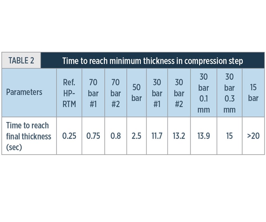
To sum up, trials were run on two variants of ICT’s PC-RTM process. Variant #1 was based HP-IRTM and variant #2 was based on HP-CRTM. The main difference between #1 and #2 was the initial mold position before injection start. Either it is controlled by press force (#1) or was controlled by a gap in the mold (#2). Although the low-pressure HP-CRTM process (variant #2) avoids potential pitfalls associated with high pressure build up during injection, it is also significantly slower. Table 2 shows the time to reach minimum thickness in the compression step, with both pre-defined end gap processes being the slowest, compared to the HP-IRTM variants (#1) at pre-set pressures.
Results look promising
The initial study demonstrated the ability of ICT’s PC-RTM process to control cavity pressure at high flow rates. Further, all of the parts, admittedly of flat, noncomplex geometry, were fully impregnated without voids or fiber distortion, with an average fiber volume of 58% and a thickness tolerance of ±0.05 mm. More importantly, Rosenberg reports, it set the stage for developing and extending the technology to more complex parts, particularly foam-cored structural parts aimed at automotive applications, such as body floor panels.
In the follow-up SMiLE project — System-integrative Multi-material Lightweight design for Electro mobility (03X3041A) — funded by the German Federal Ministry of Education and Research, the PC-RTM variant was implemented in the ultra-RTM process chain from partner Audi AG (Ingoldstadt, Germany) to manufacture a technology demonstrator part with lightweight PU-foam cores and a complex geometry consisting of different sub-preforms. That study is finished,” says Rodenberg, “and we made the complex part at high flow rate together with the low in-mold pressure of 15 bar. The press force was reduced by 75% compared to IRTM.” ICT’s and Audi’s partners included FRIMO Group GmbH (Lotte, Germany), BASF Polyurethanes GmbH (Lemförde, Germany), Voith Composites GmbH & Co. KG (Garching, Germany), KIT-wbk and KIT-FAST (Karlsruhe, Germany).
Although it would be feasible to use more expensive sandwich core structures that withstand higher pressures, the higher material costs make that option prohibitive for high-volume applications. Rosenberg reports the team at the Institute, along with its partners, are currently in the final stages of the project with a goal to build a full-scale demonstrator integrated floor panel, roughly 1.5m by 1.4m, via PC-RTM, with high flow rate and a total cycle time of less than 5 minutes.
“The problem we are facing right now is, that the maximum output (flow rate) of a HP-RTM machine with one mixing head is about 160 g/sec,” says Rosenberg. “For big parts, which need, maybe, 4 kg of resin amount, we need even higher flow rates to reduce the injection time to, maybe, 15 sec.”
The tangible progress made in the early stages of this project has proved the potential in-mold cavity sensing technology has to substantially increase throughput, efficiency and consistency in autocomposites manufacturing. Looking forward, Rosenberg says, “The goal is definitely to reduce equipment size/cost.” Accomplishing fast injection and thorough impregnation of complex preforms under relatively low pressures in HP-RTM systems would have cascading benefits: Low pressure requires lower press force and mid-pressure or even low pressure injection equipment could be sufficient. Further, reduced press force and low pressure would reduce energy costs, and could save tooling cost as well because molds could be designed from less stiff (and therefore, expensive) materials. Moreover, the auxiliary functions, such as vacuum ports or ejectors, could be designed to accommodate as little as 30 bar, instead of having to handle up to 150 bar.
Related Content
PEEK vs. PEKK vs. PAEK and continuous compression molding
Suppliers of thermoplastics and carbon fiber chime in regarding PEEK vs. PEKK, and now PAEK, as well as in-situ consolidation — the supply chain for thermoplastic tape composites continues to evolve.
Read MoreSmartValves offer improvements over traditional vacuum bag ports
Developed to resolve tilting and close-off issues, SmartValves eliminate cutting through vacuum bags while offering reduced process time and maintenance.
Read MoreMFFD thermoplastic floor beams — OOA consolidation for next-gen TPC aerostructures
GKN Fokker and Mikrosam develop AFP for the Multifunctional Fuselage Demonstrator’s floor beams and OOA consolidation of 6-meter spars for TPC rudders, elevators and tails.
Read MoreNovel composite technology replaces welded joints in tubular structures
The Tree Composites TC-joint replaces traditional welding in jacket foundations for offshore wind turbine generator applications, advancing the world’s quest for fast, sustainable energy deployment.
Read MoreRead Next
All-recycled, needle-punched nonwoven CFRP slashes carbon footprint of Formula 2 seat
Dallara and Tenowo collaborate to produce a race-ready Formula 2 seat using recycled carbon fiber, reducing CO2 emissions by 97.5% compared to virgin materials.
Read More“Structured air” TPS safeguards composite structures
Powered by an 85% air/15% pure polyimide aerogel, Blueshift’s novel material system protects structures during transient thermal events from -200°C to beyond 2400°C for rockets, battery boxes and more.
Read MoreDeveloping bonded composite repair for ships, offshore units
Bureau Veritas and industry partners issue guidelines and pave the way for certification via StrengthBond Offshore project.
Read More
