From frigate to luxury gigayacht
A new, all-composite superstructure built in the U.S. transforms a steel-hulled naval vessel in the United Arab Emirates into a massive, yet swift luxury yacht.
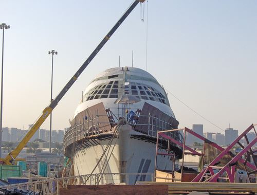
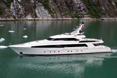
Luxury yachts tend to gain weight during construction, as designers add convenience equipment and furnishings (e.g., marble). This slows cruise speed and can negatively impact stability. On gigayachts such as the recently constructed Swift 141 — those more than 122m/400 ft in length — this problem scales up with size. Originally a Royal Netherlands Navy S-class steel frigate (similar to but smaller than a destroyer), it was sold (circa. 1997-1998) to the United Arab Emirates (UAE) and eventually became the subject of a luxury yacht conversion pilot project to showcase the emirate of Abu Dhabi’s development of a world-class yacht construction and service facility, now known as Abu Dhabi Mar. At 141m/463 ft in length, with an expected cruise speed of 25 knots, the Swift 141 should be one of the world’s fastest gigayachts, thanks to its long, narrow frigate hull and a massive refit, including what is believed to be the largest yacht superstructure ever built with composites.
Big project, big challenges
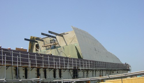
To save weight and meet speed and stability objectives, while enabling the sleek, modern design created by Paris-based Pierrejean Design Studio, engineers determined that the Swift 141’s steel superstructure should be replaced with an all-composite construction that would encompass bulkheads on the main deck and bulkheads, soles (floors) and structural members on the three upper decks. Composites also were specified for all interior soles below the main deck. The composite superstructure would effectively modularize construction and enable fabrication and assembly of the ship’s accommodations and upper decks while new hull systems were installed and hull modifications were completed, shortening overall delivery time.
In August 2007, Swift 141 project manager Johan Valentijn awarded the composites production management contract for the 100m/328-ft long, 14.4m/47-ft wide and 13.5m/44-ft high superstructure to Ft. Lauderdale, Fla.-based JFCI Composites Group. JFCI chose two subcontractors that had the unique capabilities that the job required, as well as a 10-year history of working together on large projects, to build almost 6,500m²/70,000 ft² of composite components: Vectorworks Marine (Titusville, Fla.) supplied large CNC-cut molds and their corresponding curved molded composite exteriors, and Compmillennia (Washington, N.C.) manufactured curved and flat internal bulkheads, flat and cambered sole panels, and most of the carbon-fiber-reinforced longitudinals, which together formed the interior accommodations and internal support structure.
Developed in compliance with marine vessel classification society Det Norske Veritas’ (Oslo, Norway) “High Speed Light Craft and Naval Surface Craft” code and produced in 15 months from concept to completion, the superstructure components were built in just 12 months. “We were able to rapidly prototype huge molds and molded parts extremely quickly,” says Frank Crane, JFCI’s founder and president, noting “normally, a superstructure of this size would require 12 months just to build the one-off molds.”
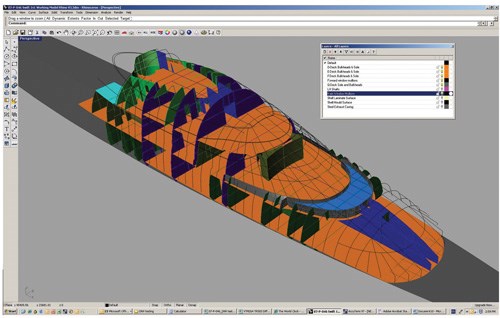
Structural composite engineers Mark Bishop and Brian Climenhaga of Waterfront Composite Solutions LLC (WCS, Fairfield, Calif.) provided more than 800 drawings. To facilitate the compressed schedule, WCS maintained a hyper-accurate three-dimensional (3-D) model and extracted construction documentation directly from it. Design and construction occurred concurrently; Vectorworks and Compmillennia completed construction as engineers electronically submitted the drawings for each section.
A key challenge for JFCI was continuous quality assurance and quality control (QA/QC) management. This entailed providing full documentation of all materials, including printed part manufacture logs that recorded date of manufacture, temperature and humidity for every part made — the latter two obtained by sensors strategically placed throughout both Vectorworks’ and Compmillennia’s manufacturing facilities.
Before production could begin, JFCI had to address one other issue: How to join the composite superstructure to the steel deck of the Swift 141’s hull. “We looked around to see what had already been done,” Crane reports, “and were fortunate to discover a similar composite-to-steel joint design evaluated for the U.S. Navy’s DDG-1000 destroyer project.” Edison Welding Institute (EWI, Columbus, Ohio) assisted JFCI in adapting and testing the solution, which eliminates bolts, relying instead on structural channels and adhesive bonding. EWI test results showed that the joint design could withstand combined in-plane static and seaway loads of at least 1,500 kN/meter at 73.4˚F/23˚C and 1000 kN/m at 140˚F/60˚C, with no internal corrosion after 60 days of hot/wet environmental exposure and 1,500 hours of salt fog exposure — enough to win the method permanent acceptance as a DNV class joint for bonding composites to metal structures.
Super-sized floors, walls & helideck
Compmillennia produced roughly 4,645m²/50,000 ft² of infused composite panels and other superstructure parts. As the company prepared to start production, JFCI Composites contracted foam supplier DIAB (DeSoto, Texas) to provide flow modeling and analysis on the first set of 3m by 12m (10-ft by 40-ft) bulkheads and to conduct onsite training for the use of its infusion core technology.
Fabrication began with the vertical bulkhead panels that form the cabin partitions and hallways on the main deck. These structural panels used Vectorply’s (Phenix City, Ala.) E-LTX 3400 (34 oz/yd²) triaxial and E-LT 3200 (32oz/yd²) biaxial E-glass fabric skins, 50-mm/2-inch thick H80 80-kg/m³(5-lb/ft³) Divinycell foam core (DIAB) with a grooved surface for infusion, and Gurit’s (Magog, Québec, Canada) PRIME 20 epoxy infusion resin. The next series were horizontal sole panels, made with the same resin and core, the latter in 60-mm/2.4-inch thickness, using Vectorply’s E-LT 3200 biaxial E-glass fabric for the skins.
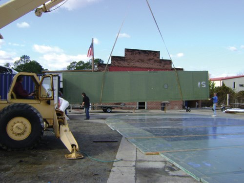
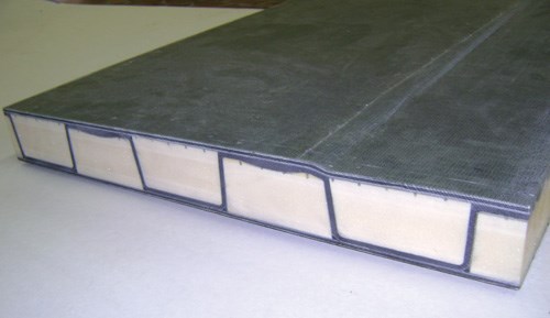
A series of cambered panels (slightly arched to shed water) comprise the helicopter landing deck. The deck’s narrow perimeter featured faceskins reinforced with Vectorply’s E-TLX 3400 (34 oz/yd²) triaxial glass reinforcements. Perimeter and interior panels were cored with an 80 kg/m³ (5.0 lb/ft³) H80 Divinycell. A central area featured panels cored with higher density 200-kg/m³ (12.5-lb/ft³) H200 Divinycell between faceskins reinforced with Vectorply’s C-BX 1200 (12 oz/yd2) double-bias fabric connected by trapezoidal carbon fiber shear webs to support helicopter landing loads. The carbon shear web-reinforced foam sandwich panels were layed up and infused in one shot to form integrated, one-piece structures. “These were very challenging structures,” recalls Compmillennia founder and president Jim Gardiner, “because the foam core and eight plies of carbon fabric in the shear webs had to be nested without bridging in the corners and the whole reinforced-foam-cored structure infused while maintaining uniform thickness and alignment in the shear webs and faceskins.” For shipping, the deck was divided into 11 transverse panels, measuring 2.5m wide by 12m long (8-ft by 39-ft), which were containerized for the trip to Abu Dhabi.
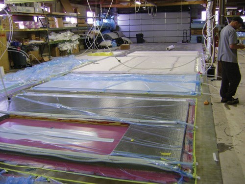
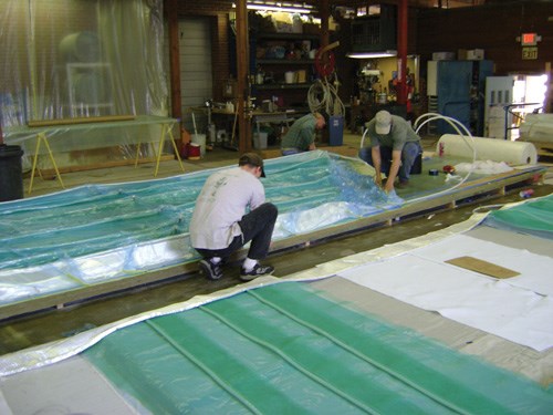
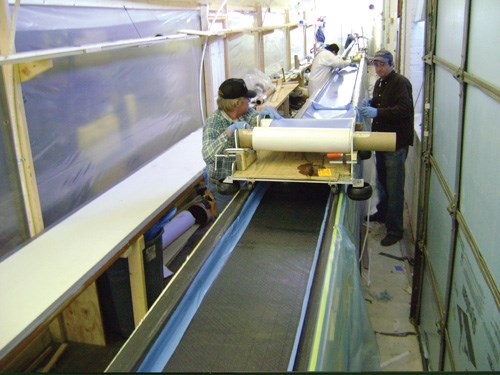
Panel processing began with an AutoCAD drawing, from which a core kit was cut to each part’s net shape. All flat panels were infused on a specially built 6m by 24m (20-ft by 80-ft) thermostatically controlled, heated mold table. The area for a given panel was prepared (multiple panels often were layed up and infused simultaneously) and then release film and peel ply laid down. Next, the dry laminate stack was layed, with time and cost saved by using 2,540-mm/100-inch wide rolls of material. Although each roll weighed 172 kg to 204 kg (380 lb to 450 lb), it was mounted on a roller and chain hoisted onto a specially built wheeled dispensing cart, enabling a single technician to transport it. After laying the bottom laminate stack, technicians applied the core, covering laminate stack, peel ply, feed lines and then vacuum bagging film. To streamline panel production, Gardiner experimented with available resin feed lines, eventually inventing his own (see sidebar, below.)
The infusion resin was stored in a 264-gallon/1,000-liter tank, maintained at 85˚F/29˚C and pumped using a Perfect Flow double-acting, high-flow resin pump made by Rook Metering/Michael Engineering (Mt. Pleasant, Mich.). To assist with troubleshooting during infusion, the resin was tinted yellow, the hardener was tinted blue and the cured resin was green. Four vacuum pumps and a standby generator were available as a backup, in the event of a utility failure in the middle of a shoot. Four hours after infusion was completed, enough time for the resin to gel, technicians elevated the table temperature and covered the panel with insulation blankets for a 12-hour post-cure at 125˚F/52˚C. Because the foam had been sized to net dimensions, demolded panels required little trimming.
High-tech beams without high-tech overhead
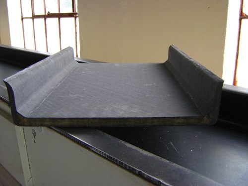
Compmillennia also produced more than 914m/3,000 ft of carbon fiber beams for Swift 141’s superstructure, measuring 15m to 35m (49 ft to 115 ft) in length, with shorter and lighter beams used higher up and further aft, where design loads were lighter. These beams — longitudinal C-channels, 400 mm/15.8 inches wide across the shear web with 75-mm/3-inch deep flanges — spanned the superstructure bulkheads and formed the fore-to-aft structural floor girders. The shear webs were 15-mm/0.6-inch thick Corecell T-500 foam core between prepreg skins of 410 g/m² (12 oz/yd²) carbon fiber biaxial fabric (SIGMATEX High Technology Fabrics, Benicia, Calif.) pre-impregnated with VTM 264 low-temperature (150˚F/66˚C) toughened epoxy resin by Advanced Composites Group (ACG, Tulsa, Okla.). The flanges were formed using 25 plies of ACG’s 400 g/m² carbon fiber prepreg unidirectional tapes (uni-tapes). The channel beam design that was supplied to Compmillennia required that the flange uni-tapes be layed up with a 1-mm/0.04-inch offset to achieve a tapered edge in the 8-mm/0.30-inch-radius corners.
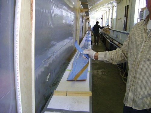
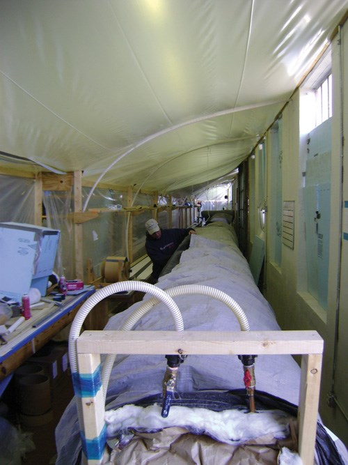
After receiving the initial beam specifications, Gardiner began work on a manufacturing process. The beams would be layed up in a climate-controlled, beam-sized cleanroom built along one side of Compmillennia’s main production building. Next, Roberts Co. (Winterville, N.C.) custom-fabricated the beam mold from steel, selected for its low cost, relatively high speed of fabrication (four days) and its robustness, because many parts would be pulled from this single mold. Expansion of the 37m/121-ft steel mold during part cure was approximately 1.0 inch/25.4 mm in overall length throughout the whole cycle, or 0.07 percent.
Gardiner then collaborated with Dana Greenwood of SYBO Composites (St. Augustine, Fla.) on the beam curing system. The two had worked together previously on a 54m/177-ft carbon fiber mast — the world’s largest at the time. They essentially recreated a computerized system that, in 1992, had successfully maintained temperature along the mast within 2˚F to 3˚F, but this time, used more modern equipment, including a computerized control unit supplied by Techni-Systems (Chelan, Wash.). The controller was wired to an array of thermistor temperature sensors and double sets of heating elements — redundancy prevented cold spots in the event of an element failure. The mold was divided into six 6m/20-ft zones, with six thermistors per zone, which enabled a quick visual scan of the computer monitor during cure to ensure temperatures were within spec. A lagging thermistor on top of the part drove temperature control, as it had to register the specified temperature through the ramp of 10˚F per 30 minutes, up to the 150˚F/66˚C soak for 15 hours and back through the ramp down to complete the cure cycle within 24 hours.
Similar to its preparation for infusion, Compmillennia again invested in training prior to onset of prepreg beam production. Abaris Training (Reno, Nev.) was brought in to conduct hands-on, onsite training for the six-person crew that would laminate and cure the prepreg beams. Compmillennia had already outlined a manufacturing procedure, using Abaris Training’s consulting service (Abaris Direct) and carbon prepreg structural design analysis by Dr. Rikard Heslehurst of Heslehurst Consulting (Macarthur, Australia), who teaches composites engineering courses for Abaris Training and is a faculty member of the Australian Defense Force Academy in Canberra. Though focused on the basics of prepreg lamination and curing, the onsite training actually walked Compmillennia’s crew through their draft manufacturing process, which basically “road-tested” it, identifying problem areas and refining the process for actual production.
One issue was how to apply 35m/115-ft long layers of carbon prepreg while maintaining fiber alignment, crucial to achieving required structural properties. Gardiner developed an inexpensive prepreg application device that rolled along the outer edges of the beam mold while simultaneously stripping off the prepreg’s paper backing and applying the biaxial prepreg accurately down the length of the mold without skewing the fibers. During pre-assembly of the five-ply kits of uni-tapes for the flanges, Gardiner used a static tensioning device to stretch the tapes under 1,000 lb/4.5 kN of force to keep fibers straight and maintain required tolerances in the 1-mm/0.04-inch offsets. This was done on a mold-sized cleanroom work surface in parallel to beam production. Thus, while a beam was laminated, cured and demolded and the mold was being prepared for the next beam, the uni-tape layers for that next beam were kitted, reducing the overall cycle time.
After mold preparation, using an in-mold cleaner and release system supplied by Zyvax (Ellijay, Ga.), technicians laid one ply of the biaxial carbon fabric into the mold and then applied the pre-assembled uni-tape kit to the flanges. The layup was then vacuum-bagged and debulked for approximately 15 minutes using a mesh breather. This cycle was repeated five times, after which a film adhesive and Corecell foam core was placed, followed by five more plies of biaxial fabric, with debulks every two plies until the final vacuum bagging and cure. After the beam was demolded, its flanges were trimmed and for the beams that would cross bulkheads and, therefore, need a bearing surface, carbon prepreg doublers were secondarily bonded, using Pro-Set 176/276 toughened thixotropic epoxy resin system, from Pro-Set Inc. (Bay City, Mich.)
The 6,000-mile question
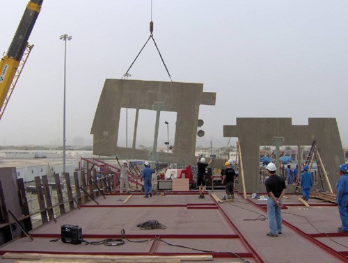
As parts were completed, they were packaged, placed in containers and transported by ship to the assembly site at Abu Dhabi Mar, where they were assembled by a team of 30 technicians from all over the world. JFCI and partners credit Waterfront Composite Solutions’ “everything from 3-D” approach to the engineering drawings with virtually eliminating errors and omissions, enabling production of parts with very little rework — a big plus given the 6,000 mile (9,656-km) distance between the U.S. part manufacturer and UAE assembly operations.
The Swift 141 deck was laid out for the bulkhead and exterior shell intersections. Channels were formed to secure them, using 10 mm by 75 mm (0.39-inch by 2.95-inch) steel flat bar stock. The channels featured a 2-mm/0.08-inch gap for adhesive and were then sandblasted, acid-etched and primed with a DNV-approved, unfilled epoxy primer made by 3M (Minneapolis, Minn.). After the bulkheads were installed in the channels, technicians set-up and infused the connection, using a 3M Scotchweld epoxy adhesive. This same method was used to join the composite exterior to the hull’s steel bulwarks (a vertical fence-like structure that encompasses the upper edges of the deck), but with 316L stainless steel bar to form the channel along the outboard edge, ensuring no corrosion would form in this difficult-to-access area.
What comes after giga?
At press time, Abu Dhabi Mar, now an established facility, continues work to finish out the Swift 141 and has announced plans to convert a second frigate into the 135m/443-ft Swift 135. Likewise, JFCI and its subcontractor partners see an opportunity to recreate their Swift 141 success with future large yacht projects as well as nonmarine ventures requiring super-sized composite structures.
Editor’s note:Contributing writer Ginger Gardiner, who wrote this article, is married to Jim Gardiner, president of Compmillennia and one of the sources for this story.
Related Content
From the CW Archives: Airbus A400M cargo door
The inaugural CW From the Archives revisits Sara Black’s 2007 story on out-of-autoclave infusion used to fabricate the massive composite upper cargo door for the Airbus A400M military airlifter.
Read MoreComposite resins price change report
CW’s running summary of resin price change announcements from major material suppliers that serve the composites manufacturing industry.
Read MorePlant tour: Albany Engineered Composites, Rochester, N.H., U.S.
Efficient, high-quality, well-controlled composites manufacturing at volume is the mantra for this 3D weaving specialist.
Read MorePEEK vs. PEKK vs. PAEK and continuous compression molding
Suppliers of thermoplastics and carbon fiber chime in regarding PEEK vs. PEKK, and now PAEK, as well as in-situ consolidation — the supply chain for thermoplastic tape composites continues to evolve.
Read MoreRead Next
FEA facilitates custom megayacht design
Modeling software and design ingenuity meet vibration challenges in ocean-going luxury yacht.
Read MoreAll-recycled, needle-punched nonwoven CFRP slashes carbon footprint of Formula 2 seat
Dallara and Tenowo collaborate to produce a race-ready Formula 2 seat using recycled carbon fiber, reducing CO2 emissions by 97.5% compared to virgin materials.
Read MoreVIDEO: High-volume processing for fiberglass components
Cannon Ergos, a company specializing in high-ton presses and equipment for composites fabrication and plastics processing, displayed automotive and industrial components at CAMX 2024.
Read More

