Heatshield for Extreme Entry Environment Technology (HEEET): A broader mission
3D woven fabric enables scalable, tailorable heatshield that cuts cost, boosts performance for future spacecraft.
The heatshields that protect spacecraft structure and payload from the intense heat of entry into a planet’s atmosphere are critical components and, historically, have been uniquely developed, at great cost, for each mission. That’s something the Heatshield for Extreme Entry Environment Technology (HEEET) team at NASA is seeking to change. It has developed a family of constituent thermal protection system (TPS) materials that can be used on multiple spacecraft intended for multiple destinations, reducing the design time and cost per shield and mission. HEEET also aims to reduce heatshield weight, cutting mass by up to 50%, with a corresponding reduction in G loads (gravity forces) on the spacecraft.
The key to HEEET’s performance is a dual-layer, carbon fiber and phenolic fabric. Dual-layer TPS systems have been proposed before, with layers bonded, says Don Ellerby, research scientist at NASA Ames Research Center (Mountain View, CA, US). “But the challenge they faced was what to bond them with that will survive the high temperatures during entry. The HEEET system gets around this by integrally weaving and interlocking the two layers.” Ethiraj Venkatapathy, NASA Ames’ principal technologist for Entry Systems and team leader for Advanced TPS development, notes that the advantages of using 3D woven fabrics in composite structures was well known. “Applying them in thermal protection systems was new,” he says.
“We wanted a materials technology that can meet the requirements of many different missions,” he adds. That meant it must enable a range of entry conditions, what NASA terms “a larger entry corridor.” Legacy carbon fiber-reinforced phenolic at high density performs well at steep, quick entries that generate high heat flux, but some missions require a shallow approach, flying longer at higher altitude to reduce the G loads on sensitive instruments. “HEEET offers this robust performance and can be adapted to enable scientific probe missions to Venus, Saturn, Uranus, Neptune and sample return missions from Mars, asteroids, comets, Europa and Enceladus,” says Venkatapathy. "It’s not just a one-shot development. It’s a broader technology.”
Evolving TPS to a 3D woven system
HEEET began with efforts to find new TPS materials in the early 2000s. “With the Galileo probe to Jupiter in 1995-1996, we used a 2D carbon fiber fabric system impregnated with phenolic resin,” recalls Venkatapathy. It was capable, but the source material was no longer available. Therefore, a search began for alternative materials.
Around this time, the Adaptive Deployable Entry system ProjecT (ADEPT) — which used carbon fiber (CF) fabric in a deployable, umbrella-type heatshield — required a vendor to manufacture and support the development. Bally Ribbon Mills (BRM, Bally, PA, US) responded to a NASA request for information. “We started working with BRM for ADEPT and this led, eventually, to exploring a new way of making rigid and flexible TPS,” says Venkatapathy. The next project, “3D Multifunctional Ablative TPS (3D-MAT) for Orion Compression Pad,” began in 2012. “We chose quartz fiber because it has low thermal conductivity and is a resilient fiber, not as brittle as carbon,” he explains. NASA and BRM worked to produce a 3D woven fabric that was infused with resin to form the compression pads now flying on the Orion spacecraft.
From there, the objective shifted to a heatshield system design that could be tailored and applied across many missions. For that, notes Venkatapathy, “carbon fiber is good at handling heat flux, but it is highly conductive, and we needed a system that was insulative as well.
Two-layer, 3D-weave
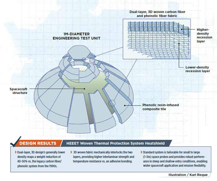
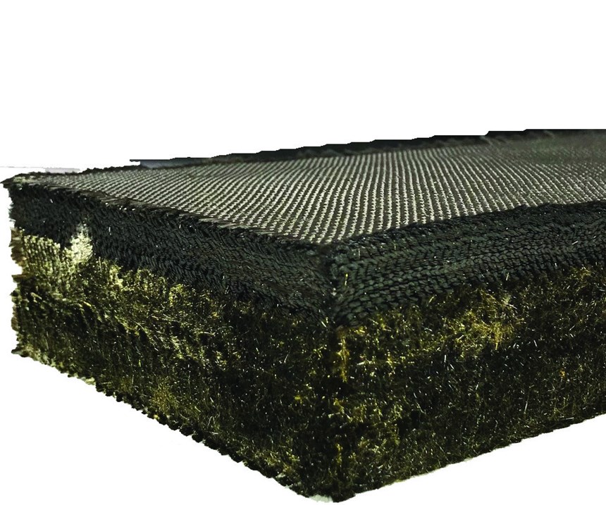
“We decided to differentiate the top layer from the bottom layer,” Venkatapathy explains. “The top layer, exposed to high heat flux, would be pure carbon fiber and very dense.” It would re-radiate heat and act as an ablative layer, burning away in a controlled manner, carrying heat away from the spacecraft, while leaving char to provide insulation. The bottom layer would be less dense and mix CF with lower-density phenolic yarn to act as an additional insulating layer. “We looked at various weaves as well as types of carbon fiber and other yarns,” he adds. Six-inch samples were tested over two years for aerothermal performance, using an arc jet (hot plasma) wind tunnel that mimics spacecraft-entry conditions.
AS4 carbon fiber (Hexcel, Stamford, CT, US) was chosen due to its wide availability. For the CF/phenolic hybrid, a commingled yarn was produced by carding and stretch-breaking the two fiber types, then blending the filaments. “The phenolic pyrolizes and goes away so that only char is left, basically the same as carbon fiber,” Ellerby explains.
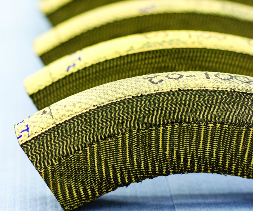
The selected weave was a 0°/90° fabric, interconnected layer-to-layer, says Curt Wilkinson, program manager for NASA woven TPS at BRM. “The char we achieve is similar to the older style of carbon fiber/phenolic material, even though the density of our system is 40-50% less,” says Venkatapathy. “This is what the 3D weave achieves — strength from layer to layer [interlaminar strength].”
The weave pattern wasn’t difficult, says Wilkinson, but achieving the density NASA required was daunting. The number of yarn ends that might typically be introduced into a loom for an entire fabric — 1,400 — was the count per inch for the HEEET fabric. And NASA wanted a 24-inch width. “We had to design and build a new loom.”
Resin-infused tiles and gap-fillers
The next steps involved fine-tuning the woven fabric’s layers and designing the composite parts. The two were interdependent. Because the issues confronted in designing the fabric layers require an understanding of the heatshield construction, the latter is described first.
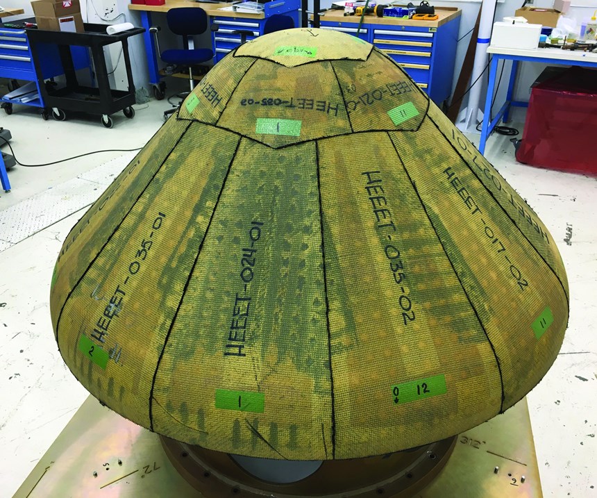
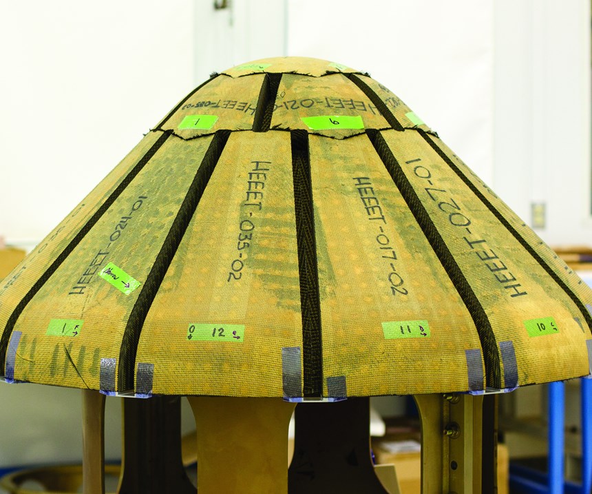
Shield geometry is fairly standard — a flat top (nose) and curved sections comprising a 45° cone. However, shield size can vary with that of the spacecraft, determined by mission scope and distance. Today, that can range from the 1m-diameter Saturn probe to a probable 3m Venus lander. “This drove a tiled design for the heatshield construction, which had to be scalable,” says Ellerby. The team used the Saturn probe as the design basis for an engineering test unit (ETU), completed in February 2018 and now in final testing and post-test analysis.
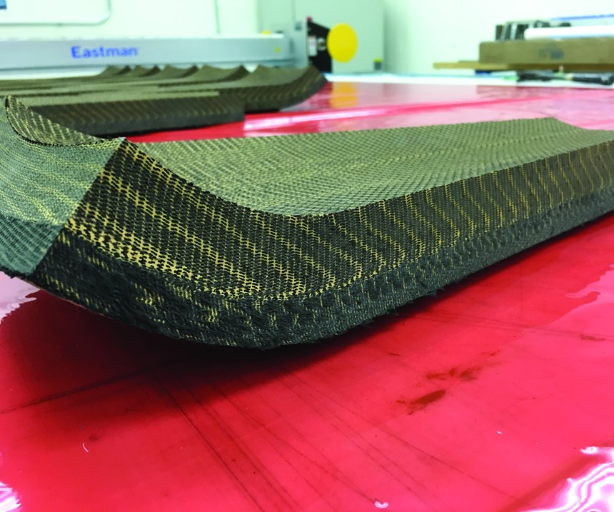
The ETU comprises 22 cone sections, each a composite tile made by infusing cut and formed 3D woven fabric with phenolic resin. However, Ellerby explains, “the composite is not completely filled with resin, because we don’t need a fully dense, resin-infused material. That’s just extra weight.” Developed by the HEEET team, the resin infusion process was transferred to Fiber Materials Inc. (FMI, Biddeford, ME, US), which has decades of experience building NASA heatshields, and fabricated the ETU components. “One of our objectives was to transfer the HEEET manufacturing processes into industry to establish the industrial base for future missions,” Ellerby explains.
Completed tiles were then bonded to the spacecraft structure, but there remained the issue of joining the tile edges. If hot gases can penetrate tile joints, the heatshield will disintegrate. “What you put between those tiles became the biggest challenge for both structural and aerothermal requirements,” Ellerby confirms.
“The material we use to fill the gaps is essentially the same as for the tiles and woven on the same loom,” says Venkatapathy. When FMI cut the BRM fabric into 22 tiles, it also cut 30-plus gap fillers. However, the gap fillers received an extra step to make them more compliant. All parts were then machined and sent to NASA for assembly.
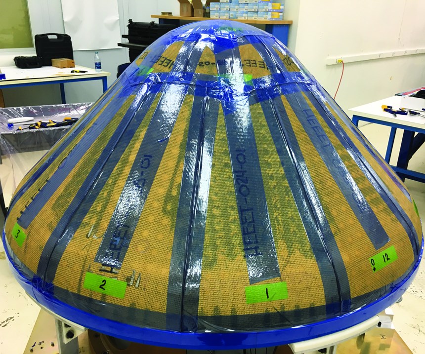
Tiles were placed and bonded to the underlying spacecraft structure using Solvay Composite Materials’ (Alpharetta, GA, US) high-temperature (resistant to 500°F/260°C) HT 424 film adhesive. The assembly was taped to hold the parts in place, then vacuum-bagged and oven-cured. “We install the tiles oversize and then route out channels at the edges into which we place the gap fillers, using a nitrile phenolic film adhesive,” Ellerby describes. The bonded gap fillers also were taped in place, vacuum bagged and oven-cured.
HEEET’s final dual-layer design was driven by two key constraints. The first was to maintain the temperature at the TPS-structure bondline below the film adhesive’s 500°F maximum. “We had an added constraint where we didn’t want to expose the insulation layer during entry,” Ellerby explains. “In other words, we didn’t want the outer layer to recede all the way through. These two constraints drove the sizing of the ablative vs. insulating layer.” For the ETU, final thicknesses were as follows: recession layer, 1.5 cm; insulating layer, 3.8 cm.
Fine-tuning layers for future performance
Although HEEET’s interlocked layers improve aerothermal performance, they were challenging to model. But, Ellerby says, “We have developed both structural and aerothermal models of the system, providing the tools future missions will need to design with. We can determine the thickness of the layers for each mission and spacecraft, accounting for factors, such as the atmosphere of the planet we are entering, vehicle shape and entry speed.”
“Having one system, which can be tailored, drives down qualification and certification costs,” says Venkatapathy. Another cost savings is in testing. “In the baseline design, the insulation layer is never exposed, thus, it didn’t need to be tested alone,” Venkatapathy explains. “It added another design constraint that was a bit more difficult to model, but the testing was simpler, almost halving the number of tests required.”
Venkatapathy concedes there are limits to HEEET tailorability. “Right now, we are only varying thickness of the two layers. Our computer models don’t currently allow changing the fabric layer densities.” But Ellerby points out that there are so many parameters that potential combinations are almost infinite. “We screened a lot of weaves and densities and chose a combination that addressed the higher priority missions. While there are certainly missions that could benefit from increased tailorability, we had project milestones and a limited budget.” He says the computational material science tools to vary all of the parameters simultaneously is still in development. “Ultimately, our vision is to have this complete tailorability,” says Venkatapathy.Related Content
Braskem demonstrates PP solutions using Weav3D composite lattice technology
Partnership combines Braskem’s polypropylene sheets with Weav3D Rebar for Plastics technology to address new structural, automotive applications requiring high-strength, lightweight material solutions.
Read More3D-woven composites find success in aerospace, space
CAMX 2024: Bally Ribbon Mills experts are displaying the company’s various joints, thermal protection system (TPS) technologies and other 3D woven composites for mission-critical applications.
Read More3D weaving capabilities achieve complex shapes, reduce weight and cost
JEC World 2024: Bally Ribbon Mills is displaying film-infused 3D woven joints, woven thermal protection systems (TPS) and woven composite 3D structures.
Read MoreComposite resins price change report
CW’s running summary of resin price change announcements from major material suppliers that serve the composites manufacturing industry.
Read MoreRead Next
“Structured air” TPS safeguards composite structures
Powered by an 85% air/15% pure polyimide aerogel, Blueshift’s novel material system protects structures during transient thermal events from -200°C to beyond 2400°C for rockets, battery boxes and more.
Read MoreDeveloping bonded composite repair for ships, offshore units
Bureau Veritas and industry partners issue guidelines and pave the way for certification via StrengthBond Offshore project.
Read MoreVIDEO: High-volume processing for fiberglass components
Cannon Ergos, a company specializing in high-ton presses and equipment for composites fabrication and plastics processing, displayed automotive and industrial components at CAMX 2024.
Read More

