Low-volume thermoplastics: Differential pressure molding
Cost-effective tooling and presses enable semi-automated prototyping and low-volume production of thermoplastic composites.
Two of the biggest challenges in thermoplastic-composite molding are the high cost of metal tooling and the long lead times required to produce tools. Aside from the complexity of parts these processes are capable of producing, the tooling also is costly because of the high pressures typically generated by the presses on which the tooling is mounted. This is particularly true for big parts. With the exception of thermoforming/vacuum forming or low-pressure thermostamping of lofted glass-mat thermoplastic (GMT) composites, most thermoplastic-composite forming is done in high-speed, high-pressure processes — namely, injection or compression molding.
Although it’s possible to prototype parts in Kirksite (zinc alloy) or epoxy tools, production tools are nearly always aluminum (for compression molding) or P20 steel (for compression or injection molding). When production volumes are moderate to high and/or part designs are complex, this cost can be justified. Complex parts allow designers to take advantage of opportunities for parts integration that, in turn, helps offset tooling costs by eliminating secondary assembly and/or finishing steps. However, when volumes are low or geometries are less complex, a capital investment in metal tools and powerful presses can’t be justified. Such parts, then, are typically designed for thermoset composites or metals. What the thermoplastic side of the composites market has needed for some time is a reliable way to form good parts at low-to-moderate production volumes cost-effectively, without having to make them by hand.
A thoroughly proven “new” process
It’s not broadly known outside of Detroit, but there is a process that, proponents say, does just that. In fact, it’s been used for more than a decade as a low-cost prototyping process to test part and tool designs destined for high-speed compression molding. It also has been used to produce a variety of commercial parts in low-to-moderate volumes for applications as diverse as automotive, heavy truck, luggage, office furniture and architecture.
This thoroughly proven but relatively unknown process is called differential pressure molding (DPM). Its inventor and patent holder, Jack Van Ert, is president of Vantage Technologies (China Township, Mich.). A former director of technology at Lear Corp. (Southfield, Mich.), Van Ert developed the process 13 years ago, while he was still at Lear, to produce automotive headliners at startup facilities in developing countries. The time he spent as a Peace Corps volunteer in rural Africa made Van Ert well aware of the challenges such operations could face, so every effort was made to take complexity, size, weight, energy requirements and cost out of both the press and tooling. The result is a highly competitive process for forming thermoplastic composite parts in developing and developed countries, and one practical for programs that require a few hundred to a few hundred-thousand parts per year.
In essence, DPM is a low-pressure, low-energy, compression-type molding process with excellent repeatability and reproducibility (R&R) values. It makes use of a pressure differential between the inside and outside of the tool to shape sheet-form composites quickly and cost-effectively. It also provides the option of bonding/comolding one or both sides of the composite with a wide variety of face materials/skins in a single step.
One of many unique aspects of the process is that it applies uniform pressure over the entire surface of the tool, yet the molding forces are low enough (0.5 to 50 psi/3.45 to 345 kPa) to be supplied by simple water or air pressure. (Deprived of a vacuum pump at one remote site, Van Ert powered one of his systems with a Shop-Vac and reports that it worked well.) Pressure can be applied either from inside the tool (negative-pressure molding) or from outside the tool (positive-pressure molding).
Another interesting aspect of DPM tooling is that unlike solid steel or aluminum compression molds, which are designed to maintain a specific gap based on a specific material thickness, DPM tools can run on force without stops (stops can be used but are not necessary). This permits the trial use of a wider variety of materials (and charge thicknesses) without necessitating tooling changes — an ideal situation for prototyping operations.
Sheet material is placed in the tool and, as the tool closes, the mold halves stop moving against each other when the pressure reaches equilibrium. Further, the mold can open and close vertically (like a compression press) or, thanks to its low weight, it can be mounted on a pivot. The process lends itself to molding reinforced or unreinforced monolithic sheet (all types of GMT with short or long chopped glass, unidirectional or woven glass and even natural fiber); sandwich-panel composites using a variety of cores; and thermoformable rigid urethanes (TRUs). Although it is optimized for thermoplastic matrices, DPM also has been used to mold select thermosets. With thermoplastics, the tool is kept cooler than the blank. The latter must be preheated just prior to placement in the tool. With thermosets, the tool is heated to a higher temperature, which is necessary to kick off crosslinking and polymerization.
Because molding pressure is low, there is very little flow of solid materials in the tool. Nevertheless, the process develops pressure sufficient to consolidate lofted materials, and thicknesses can be varied across the part simply by adding more or less material (blanks/charges) in target areas. A tooling change is not necessary. Although the low flow limits the amount of three-dimensional complexity that is possible in part designs, it consolidates/bonds multiple layers of skins/laminates during the molding cycle without overstretching or tearing the face material, thus optimizing performance, aesthetics and cost. The low pressure also greatly reduces residual stresses and postmold warpage.
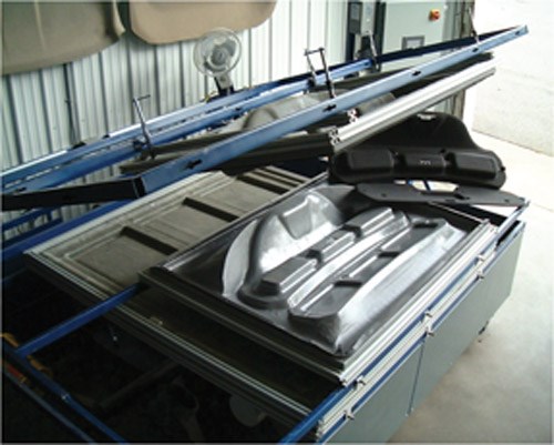
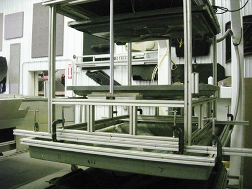
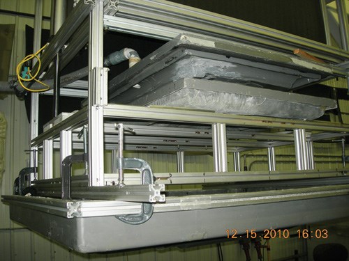
Although DPM is used most commonly to produce a single, large part, a number of smaller parts also can be molded together in a family tool and then cut apart upon removal. Another unique feature of the DPM molding process is that two or more tools can be built to operate simultaneously in the same press and mold two or more different sets of parts whose size, geometry and materials can vary significantly as long as each part is sufficiently symmetrical to balance the molding pressures within a given tool. As one tool opens and the part is demolded, the second tool is loaded and closed to form the next part, making it ideal for producing multiple versions of a given part (e.g., parts with different face materials) on a just-in-time production basis. This multitool molding option can be set up either as a stack or a pivot system. Hence, DPM offers significant process efficiencies at far lower costs and uses far less floor space than most competitive processes.
Thin-shell composite tooling is key
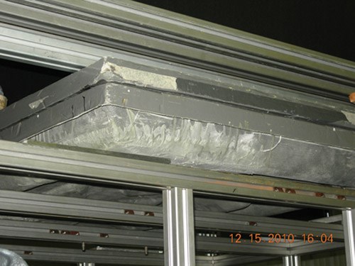
Low molding pressure also allows the use of thin-shell composite tooling. These lightweight tools can be heated and cooled much more rapidly than conventional composite or metal tools, which eliminates the need to install water lines, shortens cycle times and greatly reduces mold-cycle energy requirements, giving the process a small carbon footprint. At 30 to 90 seconds, depending on part size and geometry, the cycle times are comparable to conventional compression or injection molding. Again, because pressures are low and uniform, no steel tooling block is required, further simplifying the press in which dies are mounted.
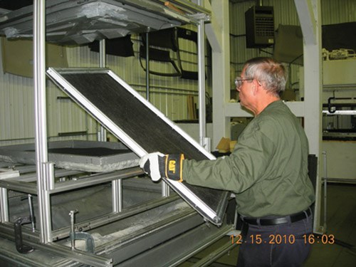
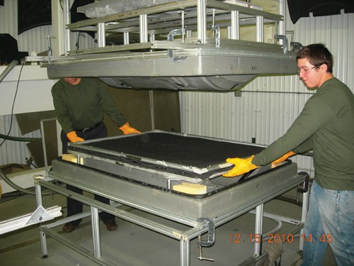
A typical DPM tool half weighs just 50 lb/23 kg (vs. several tons to several hundred tons for competitive processes). Therefore, tools are easy to change, move and store by hand without the assistance of a crane, forklift or skilled operators. Storage is equally simple. No high-strength die racks are needed, so when the tools are not in use, they can be set on their sides on the floor of the work cell.
The composite tools can be cast from an existing part, a clay or wood model or many other structures, although Van Ert says the model should be cut as an “A-surface” male and, as is true of all thermoplastic tooling, some consideration should be given to shrinkage to ensure the proper dimensions in the final parts. The first “pull” off the model is from the A-side.
Van Ert, who builds his own tooling and presses, says the typical turnaround for DPM tooling is 2 to 4 weeks vs. 6 to 12 weeks for aluminum and even longer for steel. As would be expected, his tools are far less costly, too, averaging $15,000 to $25,000 (USD) vs. $60,000 to $250,000 for competitive processes. His standard tooling resins are best for materials that mold at temperatures around 398°F/200°C. Using high-temperature tooling resins, however, he can push that to 450°F/232°C, making the process practical for high-temperature engineering thermoplastics. For very limited production runs (50 parts or less), Van Ert can reduce the tooling costs even more and reduce turnaround to 24 hours by using a different tooling resin, which sets up in as little as 30 minutes. Although these tools can’t handle prolonged heat like Van Ert’s conventional DPM molds, they are a viable option in situations where the need for speed is paramount.
Unlike tools used in high-speed compression molding, DPM tools don’t have shear edges, so parts do require some postmold trimming. As is true with conventional compression molding, through-holes can’t be formed directly in the DPM process, so postmold routing or punch-out is required. But surprisingly, it is possible to have tooling action in DPM molds. In their simplest form for prototype tools, Van Ert builds hand-placed inserts/slides that are positioned in the tool before it closes and then are stripped off the finished part when the mold opens. For more sophisticated production tools, he builds cylinders that move in and out of the tool’s side and are integrally pocketed inside the tool. This enables geometries with severe undercuts and better edge finishes.
Depending on the geometry, it also is possible to use single-sided tools and replace the second half with a rubber bladder (a common practice when molding hand-layed thermosets). Although such tooling is produced more quickly and at a lower cost, it obviously requires some design concessions (e.g., no sharp details, no variations in substrate thickness and a nonvisible backside, because the substrate material will not be flattened/consolidated well by the rubber bladder). Single-sided tools are extremely easy to modify, so this technique can be useful in early-stage prototyping. Another toolmaking option with DPM molds, and something that can’t be done in metal tooling, is the use of flexible bladders in local areas of the tool, which helps take care of an undercut without having to invest in a hard slide.
The mobile press
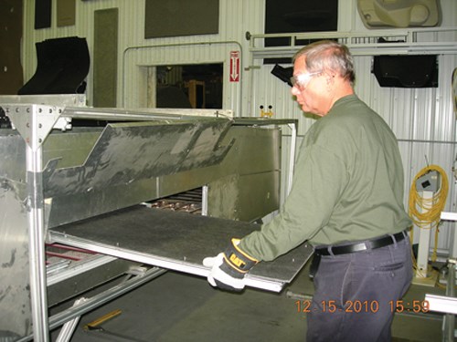
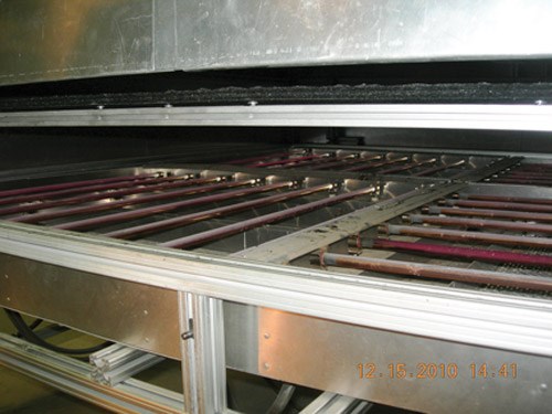
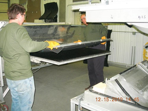
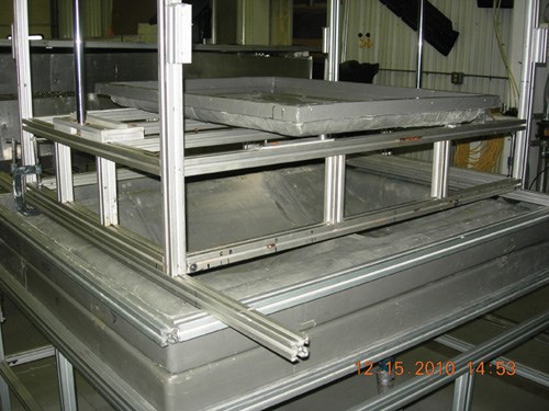
As would be expected given the lightweight molds and low applied pressures, a DPM press is a simple frame-and-clamp system/lifting device. Operated by air or water pressure, it avoids costly and maintenance-intensive hydraulics. The clamps can be operated automatically (powered by electricity or air) or manually where utilities are not available or desired. Because it is mounted on wheels, the light frame is easily moved, enabling technicians to position the press near a heating oven when it’s in use and then roll it out of the way when the job is done.
DPM press operation and maintenance are equally uncomplicated. The press is powered by a 110V/20-amp circuit, which powers both the controls and a water- or air-powered vacuum pump. Typically a 60 psi/4.14 bar pressure source is sufficient to open and close the press, which represents an 80 percent reduction in power consumption vs. a conventional hydraulic press. In operation, the press can be tended by a single person who loads material and removes finished parts, or it can be semiautomated in a work cell. In most cases, no special site preparation is required to house a DPM system. In contrast, a large compression molding press can require a high bay with a 20-ft/6m ceiling, a good foundation (to support the press and tool weight) and power requirements as high as 30 amps at 480V to run a 100-ton press — an operation that is considerably more costly and energy intensive than DPM.
Compared to conventional compression molding, a typical DPM press not only takes up considerably less floor space and headroom, it also costs half as much as a small hydraulic press and 80 percent less than a new compression-molding press. However, the output per square foot is two times higher, and that’s without the multiplier of a dual-pivot/stack setup where two or more tools are operated in the same press simultaneously. Moreover, DPM tools cost 50 percent less than tools produced with other low-volume processes, such as thermostamping/low-pressure compression molding or thermoforming, and 75 percent less than tools produced with high-speed compression and injection molding equipment, yet DPM tools can be turned around much faster.
Its low capital cost and ease of operation makes DPM ideal for production volumes of less than 100,000 parts per year and for startup manufacturing in remote sites or emerging markets where specialized facilities, equipment and trained personnel may be unavailable. In fact, DPM presses usually can be custom built on site, making it easy and cost-effective to colocate molding operations next to customer or supplier facilities in nearly any part of the world. This, in turn, helps reduce energy requirements for manufacturing operations where subsystems are produced in one locale and combined with larger modules elsewhere in the world.
Beauty cover
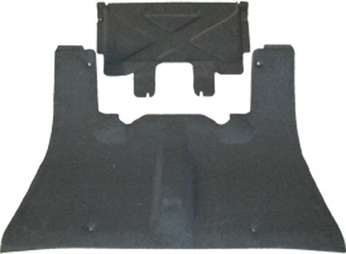
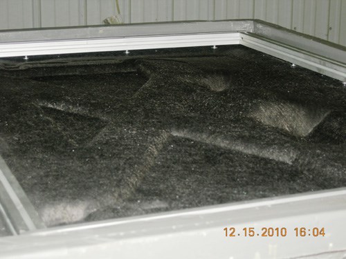
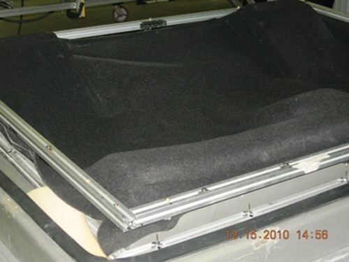
Because its tooling can be developed quickly at low cost, DPM can handle proof-of-concept and part prototyping for other compression processes. And it can produce parts for limited production runs like the two-piece “beauty cover” used on the limited edition 2012 Mustang Boss 302 Laguna Seca from Ford Motor Co. (Dearborn, Mich.). Built for racing, the car has no rear seats. When it is driven in “street” mode, the beauty cover provides an aesthetically pleasing, load-bearing floor that hides the bare chassis between the front seats and the trunk. Jointly developed by Ford and Tier 1 seat supplier The Woodbridge Group (Mississauga, Ontario, Canada) and molded by Van Ert, the cover’s parts (see photo, at right) are made from 1,400 gsm Superlite lofted GMT from Azdel Inc. (Forest, Va.). Carpet is integrally bonded to the visible surface and a polyester scrim finishes off the backside. The larger part is 48 inches by 36 inches (102 cm by 81 cm), weighs 7 lb/3.2 kg and is molded with a double thickness (to achieve 2,800 gsm) so the part is stiff enough to be knelt on without deflection. The smaller part is 32 inches by 23 inches (81 cm by 58 cm) and weighs 2 lb/0.9 kg. The parts are connected via quick-release pins under the crisscross bars that help increase rear stability during racing. Van Ert built the tools, and during the next two years he expects to produce 750 sets of parts per year, a volume that would be cost prohibitive with most other processes.
Related Content
Composite resins price change report
CW’s running summary of resin price change announcements from major material suppliers that serve the composites manufacturing industry.
Read MoreGKN Aerospace, Joby Aviation sign aerostructures agreement
GKN Aerospace will manufacture thermoplastic composite flight control surfaces for Joby’s all-electric, four-passenger, composites-intensive ride-sharing aircraft.
Read MorePEEK vs. PEKK vs. PAEK and continuous compression molding
Suppliers of thermoplastics and carbon fiber chime in regarding PEEK vs. PEKK, and now PAEK, as well as in-situ consolidation — the supply chain for thermoplastic tape composites continues to evolve.
Read MoreVIDEO: One-Piece, OOA Infusion for Aerospace Composites
Tier-1 aerostructures manufacturer Spirit AeroSystems developed an out-of-autoclave (OOA), one-shot resin infusion process to reduce weight, labor and fasteners for a multi-spar aircraft torque box.
Read MoreRead Next
“Structured air” TPS safeguards composite structures
Powered by an 85% air/15% pure polyimide aerogel, Blueshift’s novel material system protects structures during transient thermal events from -200°C to beyond 2400°C for rockets, battery boxes and more.
Read MoreDeveloping bonded composite repair for ships, offshore units
Bureau Veritas and industry partners issue guidelines and pave the way for certification via StrengthBond Offshore project.
Read MoreVIDEO: High-volume processing for fiberglass components
Cannon Ergos, a company specializing in high-ton presses and equipment for composites fabrication and plastics processing, displayed automotive and industrial components at CAMX 2024.
Read More
.jpg;width=70;height=70;mode=crop)

