
Mixed-mode fracture toughness of composites
During the 1970s, fracture toughness testing of composite materials developed a very poor reputation, primarily due to failed attempts to directly adopt metals theory and corresponding test methods. However, the basic principles of fracture mechanics remained valid.
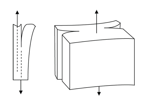
Fig. 3: Earlier mixed-mode fracture toughness test methods.
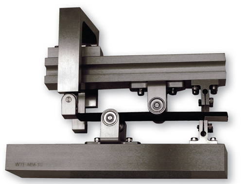
Fig. 4: Mixed-Mode Bending (MMB) fracture toughness test fixture (ASTM D 6671).
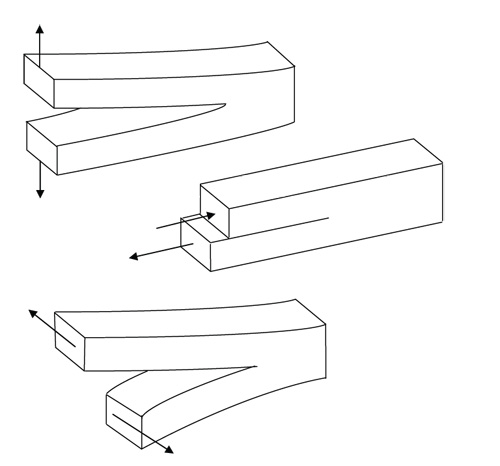
Fig. 1: Fracture mechanics failure modes.

Dr. Donald F. Adams is the president of Wyoming Test Fixtures Inc. (Salt Lake City, Utah). He holds a BS and an MS in mechanical engineering from, respectively, the University of Illinois and the University of Southern California, and a Ph.D in theoretical and applied mechanics from the University of Illinois. Following a total of 12 years with Northrop Aircraft Corp., the Aeronutronic Div. of Ford Motor Co. and the RAND Corp., he joined the University of Wyoming, directing its Composite Materials Research Group for 27 years before retiring from that post in 1999. Dr. Adams continues to write, teach and serve with numerous industry groups, including the test methods committees of ASTM and the Composite Materials Handbook 17.
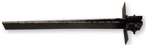
Fig. 2: Double Cantilever Beam (DCB) test specimen (ASTM D 5528).


During the 1970s, fracture toughness testing of composite materials developed a very poor reputation, primarily due to failed attempts to directly adopt metals theory and corresponding test methods. However, the basic principles of fracture mechanics remained valid. Since then, much additional research has been conducted into fracture mechanics of composite materials. One strong motivation was that so-called toughened composites were being developed during this time, and methods were required to compare and evaluate them. Although research continues today, generally accepted fracture toughness test methods are now available.
Fracture can be divided into three pure failure modes, as indicated in Fig. 1, which are conventionally indicated by the Roman numerals I, II, and III. By far, the most commonly conducted fracture toughness testing is Mode I. The so-called Double Cantilever Beam (DCB) test method, standardized as ASTM D 5528 in 19941, is well accepted. It uses a specimen (like the one shown in Fig. 2) that contains a delamination at the specimen mid-plane. The delamination is created by inserting a very thin film of nonadhesive material during the composite fabrication process. ASTM D5528 specifies a film thickness no greater than 13 µm (0.0005 inch). The choice of film material depends on the cure temperature of the composite. For example, Teflon is recommended for epoxy matrix composites cured at 177°C/351°F or less. In Fig. 2, the specimen has hinges bolted onto its end. More commonly, these hinges are adhesively bonded to the specimen. Sometimes bonded blocks are used instead of hinges. The free ends of the hinges are gripped in standard tensile wedge grips. During the test, the technician monitors the applied force, the relative displacement of the hinges, and the crack propagation length as the specimen arms are subjected to a constant rate of separation. Using the monitored data, one can calculate the Mode I strain energy release rate (fracture toughness). Details are contained in ASTM D 5528.


Mode II fracture toughness testing also is frequently conducted; however, a specific test method has yet to be standardized by ASTM. Most commonly, a specimen similar to that shown in Fig. 2, but without end attachments (hinges), is simply loaded in three-point bending. The shear stress at the mid-plane (center) of the specimen initiates the desired Mode II sliding failure (crack propagation) at the end of the insert. This test method is commonly referred to as End-Notched Flexure (ENF).
An ASTM standard for Mode III testing also is being developed. However, little Mode III testing is being conducted at this time.
Although pure-mode testing is of fundamental interest, most structural applications of composite materials involve a combination of fracture modes, particularly Modes I and II. But, how these fracture modes combine to cause failure of the structure is not well established. Thus, there has long been interest in performing mixed-mode testing. Fig. 3 indicates two of the test methods used most commonly in the early years of testing. These and several other mixed-mode test methods are presented and briefly discussed by J.H. Crews, Jr. and J.R. Reeder2,3. A major limitation of all of these test methods, however is the difficulty of determining the relative amounts of Mode I and Mode II fracture present for a given specimen configuration.
In the mid-1980s, Reeder and Crews developed at the NASA-Langley Research Center (Hampton, Va.) a much more suitable test method. They first published their work in a NASA Technical Memorandum in 19882, followed by a publication in the open journal literature in 19903. Refinements to the test fixture, essentially modifying it to the configuration standardized and in use today, were published in 19924. The governing standard, ASTM D6671, was first published in 20015. The corresponding Mixed Mode Bending (MMB) test fixture is shown in Fig. 4.
The concept is simple: The fixture simultaneously applies a direct combination of Mode I (Double Cantilever Beam) and Mode II (End-Notched Flexure) loadings. The hinges of the test specimen are clamped at the right end to both the fixture base and the loading beam. The left end of the specimen rests on a cylindrical support that is mounted in ball bearings so that it is free to rotate and, thus, not restrain lateral movement of the specimen. This support can be repositioned as required to achieve a desired support span length. The center bracket on the loading beam can be adjusted to center the loading cylinder with respect to the support span. Then, by moving the saddle at the left end of the loading beam, various ratios of Mode I to Mode II can be induced in the test specimen. For example, if the saddle is positioned above the center-loading cylinder, pure Mode II is achieved. If the center-loading cylinder were positioned above the left support and the saddle moved to the left end of the beam, then pure Mode I could be achieved. Note, however, that the fixture does not have this capability because it is simpler to perform the pure Mode I test directly, using ASTM D5528.
The MMB test fixture is gaining popularity and is, today, the preferred method for quantifying the mixed-mode fracture toughness of composites, particularly now that ASTM D 6671 is available. The test specimen is simple and of a familiar form, and the test procedure is relatively straightforward.
References
1 ASTM D 5528-01 (Reapproved 2007), “Mode I Interlaminar Fracture Toughness of Unidirectional Fiber-Reinforced Polymer Matrix Composites,” ASTM International, W. Conshohocken, Pa. (first issued in 1994).
2J.H. Crews, Jr. and J.R. Reeder, “A Mixed-Mode Bending Apparatus for Delamination Testing,” NASA Technical Memorandum 100662, NASA Langley Research Center, Hampton, Va., August 1988.
3J.R. Reeder and J.H. Crews, Jr., “The Mixed-Mode Bending Method for Delamination Testing,” AIAA Journal, Vol. 28, No. 7, July 1990, pp. 1270-1276.
4J.R. Reeder and J.H. Crews, Jr., “Redesign of the Mixed-Mode Bending Delamination Test to Reduce Nonlinear Effects,” Journal of Composites Technology & Research, Vol. 14, No. 1, Spring 1992, pp. 12-19.
5ASTM D 6671-06, “Mixed Mode I-Mode II Interlaminar Fracture Toughness of Unidirectional Fiber Reinforced Polymer Matrix Composites,” ASTM International, W. Conshohocken, Pa. (first issued in 2001).


Related Content

Damage tolerance testing of sandwich composites: The sandwich flexure-after-impact (FAI) test
A second new ASTM-standardized test method assesses the damage tolerance of sandwich composites under flexural loading.
Read More
Damage tolerance testing of sandwich composites: The sandwich CAI test
A new ASTM-standardized test method established in 2022 assesses the compression-loaded damage tolerance of sandwich composites.
Read More
Composite test methods (and specifications) for fiber-reinforced concrete structures
While initially focused on transitioning existing standards published by the American Concrete Institute, the relatively new ASTM Subcommittee D30.10 is developing new standardized test methods and material specifications for FRP composites.
Read More
Testing to support composite bolted joint analysis
An overview of ASTM Standard Guide D8509, and its coupon-level mechanical testing of design properties for analyzing composite bolted joints.
Read MoreRead Next

All-recycled, needle-punched nonwoven CFRP slashes carbon footprint of Formula 2 seat
Dallara and Tenowo collaborate to produce a race-ready Formula 2 seat using recycled carbon fiber, reducing CO2 emissions by 97.5% compared to virgin materials.
Read More
VIDEO: High-volume processing for fiberglass components
Cannon Ergos, a company specializing in high-ton presses and equipment for composites fabrication and plastics processing, displayed automotive and industrial components at CAMX 2024.
Read More
Developing bonded composite repair for ships, offshore units
Bureau Veritas and industry partners issue guidelines and pave the way for certification via StrengthBond Offshore project.
Read More