
Notched testing of composites
Open-hole test methods were developed in the early 1980s to compare toughness increases in new composite materials.

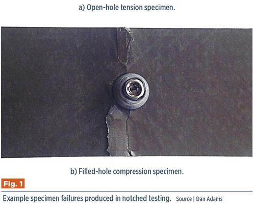
Fig. 1: Example specimen failures produced in notched testing: a) open-hole specimen, and b) filled-hole compression specimen. Source: Dan Adams
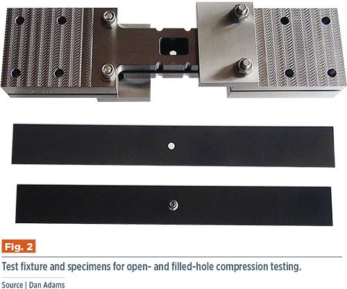
Fig. 2: Test fixture and specimens for open- and filled-hole compression testing. Source: Dan Adams


Notched testing refers to the uniaxial testing of a composite laminate with a small circular hole, under either tension or compression loading. These are commonly referred to as open-hole tests or, when a fastener is inserted into the hole, filled-hole tests. Open-hole test methods were developed in the early 1980s to compare toughness increases in new composite materials. The machined circular hole represented idealized impact damage or a manufacturing defect, enabling meaningful toughness comparisons between different materials. The notched test methods that emerged and later were standardized by ASTM1-3 all use a 36-mm wide specimen with a centered, 6-mm diameter hole, producing a width-to-diameter (w/D) ratio of 6:1. For purposes of material comparison, notched testing is typically performed using a quasi-isotropic composite laminate, consisting of equal numbers of 0°, 45°, -45° and 90° plies.
Beyond toughness comparisons, notched testing of composites serves additional important purposes today. In the aerospace industry, notched testing is used in the design of composite structures to determine the reductions in ultimate strain and strength allowables due to the presence of holes. In contrast to metals, for which stress concentrations and strength reductions due to holes are relatively simple to calculate, composites present a much greater challenge. For starters, the directionally dependent stiffness properties of composite laminates significantly increase the complexity of stress concentration calculations. Additionally, the damage states produced around holes in composite laminates are significantly more complex than the yielding produced around holes in metallic structures. These damage states also are dependent on the composite material, the laminate, the ply-stacking sequence and the loading direction (tension or compression). Given these complications, the strength reductions that will result are extremely difficult to predict, even using current state-of-the-art finite element analysis (FEA) methods. Therefore, notched testing continues to be used to experimentally determine these strength reductions. In fact, open-hole tension and compression tests are commonly used to calibrate progressive damage model parameters for use in subsequent FEA of composite structures. Open-hole testing is favored, due to the stable and detectable damage progression produced in the region of the hole as well as the ability to produce different damage progressions and strength reductions using the same composite material by changing the laminate or ply stacking sequence.


Similarly, filled-hole testing is used to determine the strain and strength reductions produced by a fastener-filled hole under tension or compression loading. Of the two loading types, compression loading is the most commonly performed, because the fastener can transmit the compression load across the hole and, therefore, significantly affect the resulting strength.
Additionally, because laminate failure is a possible failure mode for bolted composite joints, filled-hole testing is often performed using the specific composite laminate, fastener type, hole diameter tolerance and fastener torque that will be used in the application of interest.
The ASTM standard for open-hole tension testing, ASTM D 57661, specifies the use of 200- to 300-mm long and 2- to 4-mm thick specimens. Although a [±45/0/90]ns quasi-isotropic laminate is specified as the baseline laminate for making material comparisons, other laminates of interest also may be tested. Due to the strength reduction produced in the notched region of the test specimen, bonded end tabs are not required for gripping. However, the only acceptable failure mode is one that passes through the hole (like that, for example shown in Fig. 1a, at left). The use of extensometers or strain gages to measure the strain in the specimen during loading is optional. Following testing, the open-hole tension strength is calculated based on the gross cross-sectional area of the specimen (overall specimen width times specimen thickness), disregarding the reduced area produced by the hole.
For open-hole compression testing, ASTM D 64842 specifies the use of 300 mm long and 3- to 5-mm thick specimens. Similar to open-hole tension testing, a [±45/0/90]ns quasi-isotropic baseline laminate is specified. To prevent buckling during loading, a support fixture is bolted to the specimen along its entire length (see Fig. 2, below). Staggered, V-shaped gaps are employed to separate the two ends of the support fixture, and guide plates maintain assembly alignment. The fixture incorporates a 25-mm-long cutout at the location of the specimen hole to eliminate any possible constraints that might affect damage formation or propagation. Additionally, the optional use of an edge-mounted extensometer is permitted, using semi-circular cutouts machined along the edges of the support fixture.
There are two possible methods for loading the support fixture/specimen assembly. In one, the assembled fixture may be loaded into hydraulic wedge grips and clamped. Sufficient grip pressure, however, must be applied to prevent slippage between the support fixture and the specimen faces during compression loading. For this reason, the gripping surfaces of the fixture are typically coated with tungsten carbide particles to enhance the frictional force and, thus, permit higher shear load transfer into the specimen. Nevertheless, relatively large, hydraulic wedge grips (typically 250 kN capacity or greater) are required to grip the 76-mm wide and 33- to 36-mm thick assembled fixture. Therefore, another loading method has been provided: The assembled fixture can be placed between flat compression platens and then end-loaded. When this method is employed, a portion of the compressive load is introduced directly into the specimen ends while the remainder is transferred into the specimen via shear through the gripping surfaces of the support fixture. This loading option, however, requires tighter tolerances for the flatness and parallelism of the specimen ends as well as the use of additional fixture bolts in the gripping area to provide greater clamping force and minimize specimen end-brooming. Further, as a safety precaution, some type of lateral constraint should be provided so that the fixture does not slip out from between the flat platens during compression loading.
Finally, for filled-hole tension and compression testing, ASTM standard practice D 67423 provides supplemental information for including a close-tolerance fastener in the specimen hole (see Fig. 1b, at left). Although important parameters, such as the fastener hole tolerance, installation method and torque level are not specified, the practice requires that these parameters be reported. Both protruding and countersunk (flush) head fasteners are commonly used. Note that the use of fastener-filled holes requires no changes in the test procedures for either tension or compression loading nor any alteration of the support fixture used for compression loading. However, the inclusion of a close-tolerance fastener can significantly alter the resulting notched strengths. Filled-hole tension strengths can be either higher or lower than corresponding open-hole tension strengths, depending on the composite material used, the laminate tested, the fastener torque applied and the clearance between the hole and fastener. In contrast, filled-hole compression strengths are almost always higher than the corresponding open-hole tension strengths, with the amount of strength increase dependent on the same factors as for filled-hole tension, especially the clearance between the hole and fastener.
References
1ASTM D 5766-11, “Open-Hole Tensile Strength of Polymer Matrix Composite Laminates,” ASTM International (W. Conshohocken, PA, US), 2011 (first issued in 1995).
2ASTM D 6484-14, “Open-Hole Compressive Strength of Polymer Matrix Composite Laminates,” ASTM International (W. Conshohocken, PA, US), 2014 (first issued in 1999).
3ASTM D 6742-12, “Standard Practice for Filled-Hole Tension and Compression Testing of Polymer Matrix Composite Laminates,” ASTM International (W. Conshohocken, PA, US), 2012 (first issued in 2001).


Related Content
Composites manufacturing for general aviation aircraft
General aviation, certified and experimental, has increasingly embraced composites over the decades, a path further driven by leveraged innovation in materials and processes and the evolving AAM market.
Read More
Plant tour: Middle River Aerostructure Systems, Baltimore, Md., U.S.
The historic Martin Aircraft factory is advancing digitized automation for more sustainable production of composite aerostructures.
Read More
PEEK vs. PEKK vs. PAEK and continuous compression molding
Suppliers of thermoplastics and carbon fiber chime in regarding PEEK vs. PEKK, and now PAEK, as well as in-situ consolidation — the supply chain for thermoplastic tape composites continues to evolve.
Read More
Welding is not bonding
Discussion of the issues in our understanding of thermoplastic composite welded structures and certification of the latest materials and welding technologies for future airframes.
Read MoreRead Next

“Structured air” TPS safeguards composite structures
Powered by an 85% air/15% pure polyimide aerogel, Blueshift’s novel material system protects structures during transient thermal events from -200°C to beyond 2400°C for rockets, battery boxes and more.
Read More
Plant tour: Daher Shap’in TechCenter and composites production plant, Saint-Aignan-de-Grandlieu, France
Co-located R&D and production advance OOA thermosets, thermoplastics, welding, recycling and digital technologies for faster processing and certification of lighter, more sustainable composites.
Read More
Developing bonded composite repair for ships, offshore units
Bureau Veritas and industry partners issue guidelines and pave the way for certification via StrengthBond Offshore project.
Read More