Shear test methods: Iosipescu vs. V-Notched Rail
Dr. Don Adams asks and suggests a likely answer to the question Which shear test method is best?
The Iosipescu Shear and the V-Notched Rail Shear test methods are ASTM standards, ASTM D 53791 and D 70782, respectively. Both are used primarily for in-plane shear testing, but each can be used for interlaminar shear testing as well. Thus, the frequently asked question is, Which method is better?
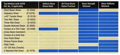
This is a slightly different question than the one I asked in my July 2005 column, which was, Why do we need another shear test method for composite materials? ASTM had released the V-Notched Rail Shear test method a few months earlier, and both test methods were discussed in detail (see chart on p. 14). Then, as promised, all of the commonly used shear test methods were compared in my next column (September 2005; see “Editor's Picks,” at right). The closing sentence of the latter was, “For generating accurate shear properties design data, the Iosipescu Shear and V-Notched Rail Shear test methods are the obvious choices.”
It was noted, however, that the V-Notched Rail Shear test method was very new, and that it was not yet clear how widely accepted it would become. Now, almost five years later, that method is well accepted, and it is appropriate to address the methods’ relative merits.
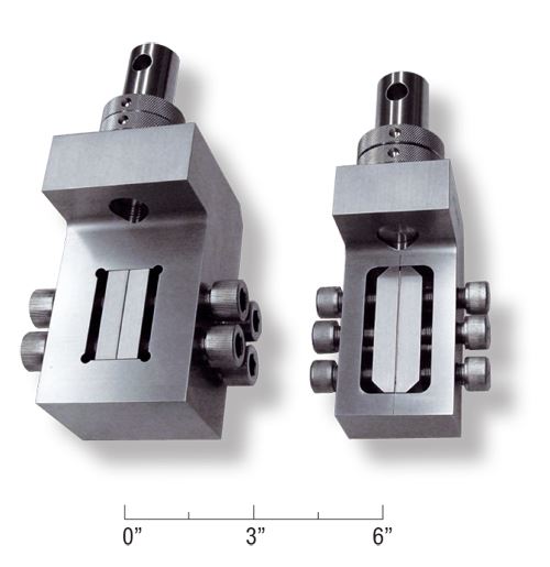
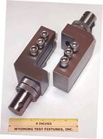
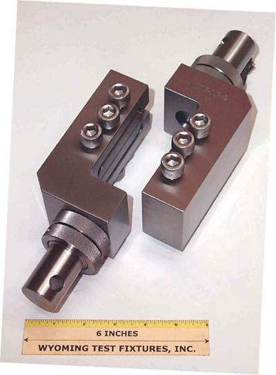
The older Iosipescu Shear method was standardized by ASTM in 1993 and has been used extensively by the composites testing community since the mid-1980s. In its quarter-century of use, it has proven to be very accurate and reliable. The test fixture is shown in Fig. 1, at right.
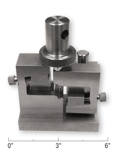
Standardized by ASTM in 2005, shortly after its development, the V-Notched Rail Shear test has a relatively short history, but its use has grown rapidly. The test fixture is shown in Fig. 2.
The principal features of the two test methods are listed in the accompanying chart. Test method designers deliberately increased the width of the V-Notched Rail Shear specimen relative to that of the Iosipescu Shear specimen to provide a larger zone of uniform shear stress between the notches. A similar width increase is not possible for the Iosipescu Shear specimen unless the specimen length is increased proportionally because the concentrated loadings on the specimen edges would become unacceptably high, risking edge crushing. For the V-Notched Rail Shear test, a specimen width increase with no increase in length is possible because face loading is much more efficient than edge loading.
In addition, the shear stress levels that can be achieved in the V-Notched Rail Shear specimen are typically three to four times higher. This might not be very important when materials with lower shear strengths (<140 MPa/20 ksi) are tested. This includes typical unidirectional and cross-ply composites and similar materials. The Iosipescu Shear test method will typically accommodate such materials, but it might be necessary to tab the specimens (to increase the load-bearing area of the edges and thus avoid crushing) as the upper limit is approached. However, laminates that have increasing percentages of off-axis plies (e.g., ±45°) tend to exhibit much higher shear strengths and cannot be tested successfully using edge loading. In these cases, the face loading used in the V-Notched Rail Shear test method is mandatory. For example, with ±45° laminates, shear stresses as high as 500 MPa/75 ksi have been achieved using this test method. The limit is reached when the specimen slips in the grip plates despite the application of maximum allowable torque on the bolts.
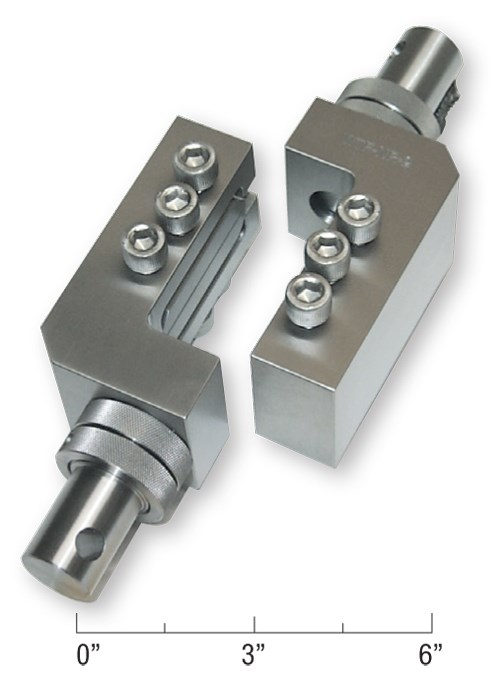
Thus, the meaningful question isn’t, Which is better? but rather, How can even higher shear forces be transferred into the specimen? One possibility is to combine the edge and face loadings into a new test fixture design, resulting in a Combined Loading Shear (CLS) test method. One fixture design that has been proposed is shown in Fig. 3. Note that the clamping plates run the full length of the holders. Thus, the holders exhibit elastic deflection symmetrically when the screws are tightened, providing more uniform clamping force.
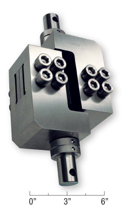
This new fixture concept is compared to the standard ASTM D 7078 fixture in Fig. 4. The concept fixture is sturdier, and the four clamping screws are larger than the three screws used in the ASTM standard fixture. Also, the widths of the cutout and the clamping plates are equal and are the same as the specimen width, 56 mm/2.2 inch. The space between grips is 25 mm/1 inch, the same as for the V-Notched Rail Shear test fixture. The fixture shown in Fig. 4 will accommodate a specimen up to150 mm/6 inches long, although users have tended to use shorter specimens as well.
Because a close fit is maintained between the specimen and the fixture, the specimen edges take the load when the specimen tends to slip under an applied force, just as for the Iosipescu Shear test fixture. The University of Utah is presently testing a fixture design with moving wedges, similar to those used with the Iosipescu Shear test fixture. This will eliminate the need for machining specimens to an accurate width.
Preliminary results indicate that the CLS fixture performs very well and could become the best answer to the question, Which test method is better?
Wyoming Test Fixtures Inc.
References
1ASTM D 5379-05, “Shear Properties of Composite Materials by the V-Notched Beam Method,” ASTM International, W. Conshohocken, Pa. (first issued in 1993).
2ASTM D 7078-05, “Shear Properties of Composite Materials by V-Notched Rail Shear Method,” ASTM International, W. Conshohocken, Pa. (first issued in 2005).
Related Content
Multi-scale 3D CT imaging enables digital twinning, high-fidelity simulation of composite structures
Computed tomography (CT) provides highly accurate 3D analysis of internal microstructure, performance simulation of carbon fiber/PEEK satellite strut.
Read MoreNumerical tool with mean stress correction demonstrated for fatigue life estimation of thermoplastic composites
To aid design of fatigue-resistant structures, Econ Engineering has developed an algorithm to evaluate ply-based cyclic stiffness degradation combined with an FE failure check, validated for a CF/PAEK pressure vessel.
Read MoreCrashworthiness testing of composites: A building block approach, Part 1
Determining the crashworthiness of composite structures requires several levels of testing and analysis, starting with coupon-level crush testing.
Read MoreDamage tolerance testing of sandwich composites: The sandwich CAI test
A new ASTM-standardized test method established in 2022 assesses the compression-loaded damage tolerance of sandwich composites.
Read MoreRead Next
A comparison of shear test methods
Dr. Don Adams compares the shear test methods that are currently available to the composite industry.
Read MoreV-Notch Rail Shear test (ASTM D 7078-05)
Dr. Don Adams introduces HPC readers to the The V-Notched Rail shear test method, approved as ASTM Standard D 7078-05 by ASTM Committee D-30 in March of 2005.
Read MorePlant tour: Daher Shap’in TechCenter and composites production plant, Saint-Aignan-de-Grandlieu, France
Co-located R&D and production advance OOA thermosets, thermoplastics, welding, recycling and digital technologies for faster processing and certification of lighter, more sustainable composites.
Read More
