Teaming to define what automotive CFRP could be
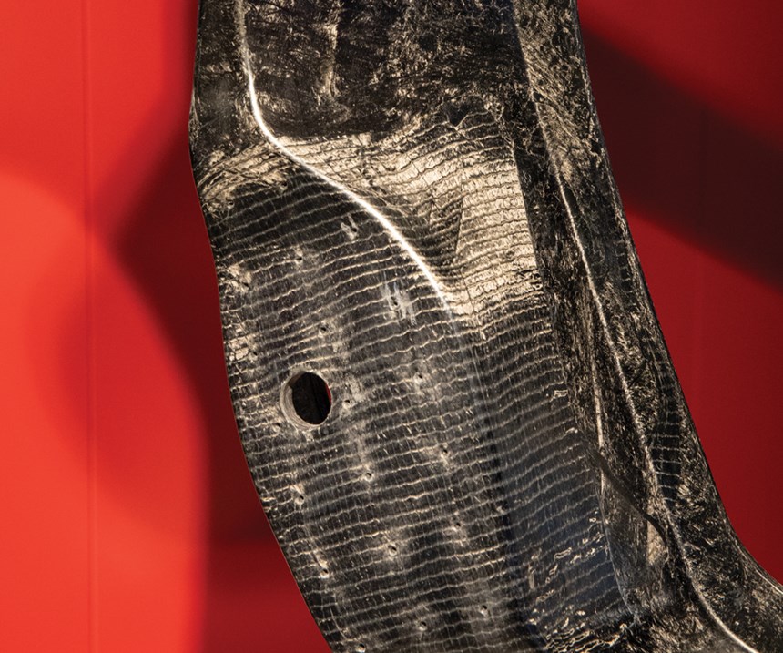
Ford and Magna explore a high-volume chassis front subframe build from co-molded chopped fiber and noncrimp fabric SMC.
Carbon fiber-reinforced plastic (CFRP) body frame/chassis components have been used in high-end sports and racing cars for decades. Their performance and lightweight enabled more recent expansion into higher volume production models, including BMW’s i3, i8 and 7 Series models, as well as Audi’s new R8 and A8 luxury sedans. However, most of these parts, including roof rails and cross members, lower side sills, B-pillars and rear walls, use continuous fiber.
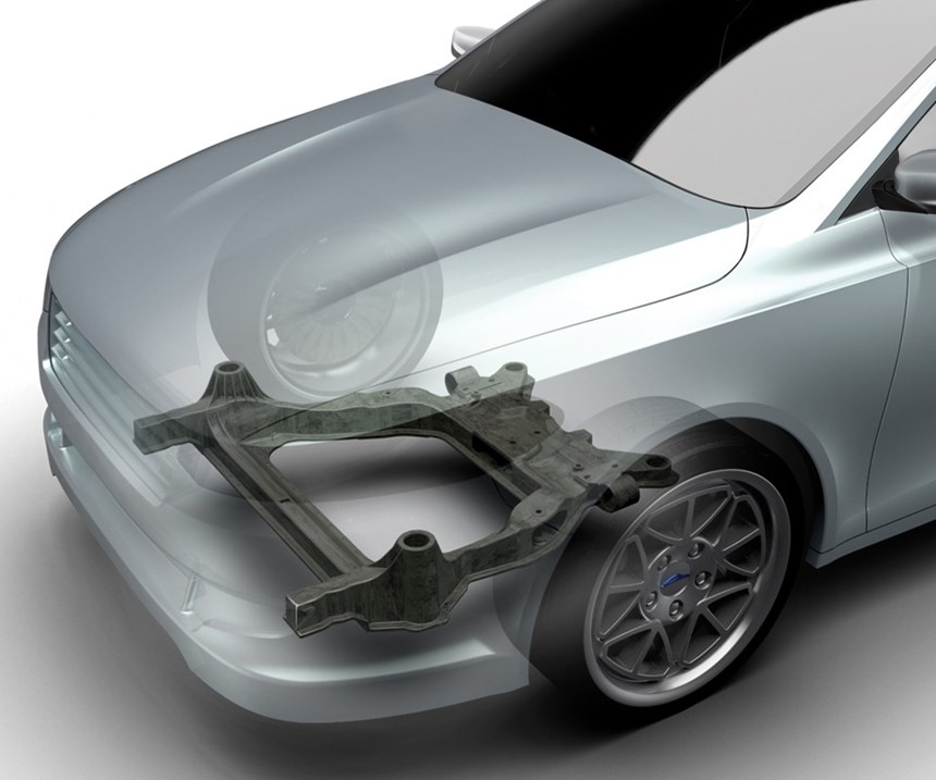
Ford Motor Co. (Dearborn, MI, US), in a joint research project with Magna International (Aurora, ON, Canada), has developed a carbon fiber composite subframe made using a sheet molding compound (SMC) that combines continuous and chopped fiber SMC. The application is novel, because the subframe, located in the front of the car, supports the engine and chassis components, including the steering gear and the lower control arms that hold the wheels and, therefore, takes significant loads.
“There were dozens of engineers involved in this project,” says Brian Krull, global director of innovation for Magna Exteriors. “We had structural engineers, manufacturing engineers, testing engineers, product engineers and computer aided engineering (CAE) specialists, as well as support from different departments at our customer, Ford, including vehicle modeling and simulation.” The Magna Composites Center of Excellence in Toronto also supported this project, “as did our body and chassis team at Cosma,” adds Cosma International global director of R&D Gabriel Cordoba.
“We wanted to explore what the challenges would be to use CFRP parts on a high-volume production vehicle,” recalls David Wagner, technical leader at Ford Motor Company. “The goal was to make as much of the structure CFRP as possible while using manufacturing that could accommodate high-volume production [200,000 vehicles/year] see how much weight that would take out and where the limits and challenges would be.”
From initial discussions to completed design, the project spanned a little over one year. Prototype subframes were delivered to Ford at the end of 2017 and are now undergoing tests.
Redefining the design envelope
The Ford Fusion’s stamped steel subframe served as the baseline. “Ford provided the design space for the project — the vehicle-level design inputs — and held weekly design meetings,” says Wagner. Cosma then took that packaging environment, Cordoba explains, “and began exploring what weight savings we could achieve. How could we retrofit the design into that space but still meet stiffness, strength and durability requirements?”
Stiffness vs. package space was an early challenge. “You typically drop modulus when you move from steel to composite,” notes Wagner, “so you need more section in the members. We defined how much the new design could change from the baseline dimensions and shared some initial topology optimization with Magna.”
Topology optimization (TO) is a CAE analysis that optimizes material placement within a given design space — including loads, boundary conditions and constraints — with the goal of maximizing performance and minimizing weight. “We started with our own TO for understanding the critical load paths,” says Cordoba. These involved loads at subframe attachment points, including control arms and engine loads, as well as road loads, engine torque twists and crash requirements.
“We had to look at our different stiffness vs. steel and the properties we wanted to have,” recalls Krull. Because composites offer many resin, fiber and fiber orientation choices, their properties can be specifically tailored, but “it is more complex than just plugging in the properties of steel,” he points out.
“Plugging in properties” refers to entering material data into software tools. “We used all of the standard software, including Nastran [MSC Software, Newport Beach, CA, US] for static analysis, Abaqus [Dassault Systèmes, Waltham, MA, US] for nonlinear static analysis, Fibersim [Siemens PLC, Waltham, MA, US] for laminate draping simulation and HyperWorks [Altair Engineering, Troy, MI, US] for TO, generating finite-element models toward analyzing different load cases,” says Cordoba.
Multiple analyses iteratively refined the modeling of the subframe for different loads, boundary conditions and materials. Krull notes that many composite materials were evaluated. “We began to look at compression molding as a manufacturing process that could provide high-volume production,” he adds. “SMC was a good fit for making this part, and we did have in-house development of carbon fiber SMC, so that is how we moved.”
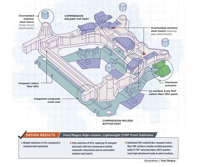
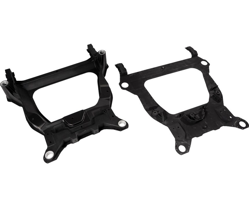
The next step was the part envelope. “The TO resulted in a box section as the best solution,” recalls Cordoba. “As we looked at the SMC compression molding process, the design that emerged was to use two parts to achieve this.” Thus, the frame comprises separately molded top and bottom halves, which are joined with polyurethane structural adhesive (Ashland, Columbus, OH, US) and rivets.
Co-molded dual SMC
Magna developed the carbon fiber SMC using its glass fiber SMC experience and a pilot line that it had acquired. “We developed proprietary technology for how we process the carbon fiber for this SMC and found we could also run NCF on that line,” Krull explains. The material is similar to prepreg in that it is impregnated before molding, but unique in that this is done on the SMC line with the same resin and, thus, termed NCF SMC. “As we refined the subframe design analyses, we used properties testing results from these materials.”
The EpicBlend SMC is compounded by Magna using chopped 50K carbon fiber tow from Zoltek (Bridgeton, MO, US) and Ashland vinyl ester resin modified in-house. The vinyl ester gives good adhesion to, and wet-out of, the carbon fiber. This would be locally reinforced and co-molded with six plies of 0°/90° NCF SMC, made by Magna with the same vinyl ester resin and NCF fabric from Zoltek, and cut into patches.
Combining the short- and long-fiber SMC was key to the design, but also a real challenge. The short-fiber SMC enables the molding of complex geometry and overmolding of the steel inserts for engine and steering mounts while the NCF patches resist high loads where the engine and lower control arms are attached. The combination of the two SMC materials cuts 9.3 kg vs. the stamped steel subframe. “It took quite a bit of work to develop the co-molding of the 0°/90° SMC patches,” Krull recalls, noting issues with how to achieve flow of the chopped fiber SMC during molding to get the NCF patches integrated without dry spots or other quality issues.
Bolted connections
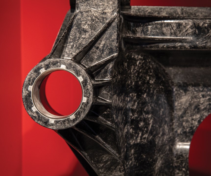
Bolted connections were also an issue. “The point loads into the composite are high — 80-100 kN — where the control arm and steering get bolted to the subframe,” says Wagner. There are four body-mount connections and two steering-mount connections where stainless steel sleeves are overmolded into the composite part. “For attachment, each body-mount bushing gets press-fit into the sleeve for an interference fit,” Krull explains. “Stress is driven into the molded part through the circumference of the sleeve. We looked at forces when the bushing is inserted and input those into the computer design models. We also looked for cracks in the composite material during the physical testing but saw none.”
Wagner points out that the bolts used are big. “These are M12 and larger, and must have tight positional, diameter and angular tolerances.” This necessitated post-machining once the subframe was molded and assembled.
Testing and teamwork
Wagner says the prototype subframes will be tested through 2018. “We hope to finish in early 2019 and publish papers on what we’ve learned,” he adds. Ford will perform a suite of corrosion tests at component and vehicle level to explore various corrosion mitigation strategies. Component and vehicle level durability tests will also be conducted, including stone impingement, testing of bolt-load retention and high-temperature cycles. Component tests will include high-cycle fatigue, joint overload, vibration and safety tests.
“We are doing our own testing of prototype subframes,” says Krull. “This is a very large, complex part to be made from SMC, enabled by the co-molding development. We are looking at how to change the design, the SMC flow during molding and fiber alignment to understand where else we might be able to use these materials.”
“We wanted to understand the largest cost drivers with this kind of CFRP-intensive part,” says Wagner. “Secondary machining is one of the most significant costs. We need to think more creatively to eliminate machining after part molding.” He also notes that one of the biggest challenges was developing the absolute material properties of the as-molded part for the design. “We spent a lot of time on material characterization to feed the design analyses,” he explains. “This was time-consuming and expensive. It was a real challenge to get from flat plaques to properties that were representative of real parts because of the material flow during the molding process.”
Cordoba says the biggest achievement is the teamwork, “not only with Ford as our customer, but as a global team. Wagner agrees: “This is a great example of how we can push our suppliers and ourselves to use advanced, lightweight materials.”
Related Content
McLaren celebrates 10 years of the McLaren P1 hybrid hypercar
Lightweight carbon fiber construction, Formula 1-inspired aerodynamics and high-performance hybrid powertrain technologies hallmark this hybrid vehicle, serve as a springboard for new race cars.
Read MorePlant tour: Joby Aviation, Marina, Calif., U.S.
As the advanced air mobility market begins to take shape, market leader Joby Aviation works to industrialize composites manufacturing for its first-generation, composites-intensive, all-electric air taxi.
Read MoreCarbon fiber, bionic design achieve peak performance in race-ready production vehicle
Porsche worked with Action Composites to design and manufacture an innovative carbon fiber safety cage option to lightweight one of its series race vehicles, built in a one-shot compression molding process.
Read MoreThermoplastic composites: Cracking the horizontal body panel nut
Versatile sandwich panel technology solves decades-long exterior automotive challenge.
Read MoreRead Next
Developing bonded composite repair for ships, offshore units
Bureau Veritas and industry partners issue guidelines and pave the way for certification via StrengthBond Offshore project.
Read More“Structured air” TPS safeguards composite structures
Powered by an 85% air/15% pure polyimide aerogel, Blueshift’s novel material system protects structures during transient thermal events from -200°C to beyond 2400°C for rockets, battery boxes and more.
Read MoreAll-recycled, needle-punched nonwoven CFRP slashes carbon footprint of Formula 2 seat
Dallara and Tenowo collaborate to produce a race-ready Formula 2 seat using recycled carbon fiber, reducing CO2 emissions by 97.5% compared to virgin materials.
Read More

