The Short Beam Shear test method for composite materials
Dr. Donald F. Adams (Wyoming Test Fixtures (Salt Lake City, Utah) suggests larger support and loading cylinders for the Short Beam Shear test method.
In my previous column, I briefly cited the Short Beam Shear (SBS) test method as a much more attractive interlaminar shear test method than the double-notch shear test method. The primary attraction of the SBS method for many users is the simplicity, the small size of the test specimen and the ease with which the test can be performed. As a result, the SBS method is widely used. Yet it is not without its detractors.
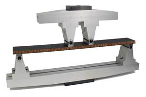
The test method loads a beam specimen in three-point bending, as shown in Fig. 1. The term “short beam” indicates that the support span length, s, is a low multiple of the specimen thickness, t. The goal is to force the beam specimen to fail in a shear mode. This can be achieved because the shear stress is independent of the support length, whereas the flexural (bending) stresses are a linear function of the support length. Thus, the shorter the beam, the greater the shear stress relative to the bending stresses.
The SBS test method was first standardized by ASTM in 1965, as ASTM D 2344, and titled “Apparent Interlaminar Shear Strength of Parallel Fiber Composites by Short-Beam Method.” The standard suggested using a support span length-to-specimen thickness ratio, s/t, of 5 for glass-fiber-reinforced composites and 4 for all other reinforcing fibers, including carbon, steel, boron, aramid and so forth. The questionable distinction for glass fibers was based primarily on some limited analytical studies that were being conducted at the time. The use of “apparent” in the title was to acknowledge that the shear stresses in the short beam are not only not uniform, but also are accompanied by tensile and compressive axial stresses as well as through-the-thickness tensile and compressive stresses. Simply put, it was well known that the SBS method was not a “pure shear” test, as would have been desirable. Nevertheless, it was considered a shear test.
In the 2000 revision of ASTM D 2344, however, the title was altered to “Short-Beam Strength of Polymer Matrix Composite Materials and Their Laminates.” The word “shear” was deleted from the title and from the definition of the strength quantity it measures. In spite of these negative implications, the SBS test continues to be used extensively for the same reason as always — it is easy to perform and can provide a good comparative assessment of material performance, even if it does not necessarily provide accurate quantitative data.
Notably, the revised method eliminated the separate s/t ratio for glass fiber composites. The standard now specifies that s/t = 4 be used for all types of fiber-reinforced polymers. And although the originally defined 0.250-inch diameter loading cylinder and 0.125-inch diameter specimen support cylinders were retained, consistent with ASTM’s decision to require “soft” rather than “hard” conversions from U.S. customary units to SI units, the SI “equivalent” diameters became 6 mm and 3 mm rather than the previous 6.35 mm and 3.2 mm.
The soft conversions raise an obvious question: Is it necessary to use different cylinders if a test is being conducted per the SI version of the standard? The strict answer, of course, is yes. But it has been clearly demonstrated during the past decade (see Adams and Busse,1 which references a number of other studies) that small changes in cylinder diameter make little difference in the test results.
Further, these studies have demonstrated experimentally and numerically that larger cylinder diameters are beneficial because they induce more uniform stresses within the beam specimen. Using small-diameter cylinders introduces high local stress concentrations. Larger cylinders spread the applied load over a wider specimen surface area, resulting in more uniform internal stress states in the specimen. In fact, it would be logical to size the cylinders in proportion to the specimen thickness and, thus, the anticipated failure load. However, this has not yet been proposed and, perhaps, is not practical. A standard loading cylinder diameter as large as 25 mm/1 inch has been suggested.1 However, considering the small thickness of a typical specimen, a loading cylinder diameter of 12.7 mm/0.50 inch, with a corresponding diameter of 6.35 mm/0.25 inch for the support cylinders, is a more practical option (Fig. 1b).
Note that, for the three-point bending SBS test depicted in Fig. 1, the reaction forces at the supports are one-half the force applied on the loading cylinder, justifying the use of smaller support cylinders. In fact, if the test specimen is relatively thin, there isn’t sufficient space between the support points to accommodate a large-diameter cylinder. For example, on a typical 2.5-mm/0.10-inch thick specimen with a support span ratio of 6, the distance between supports will be a mere 15 mm/0.60 inch, indicating that the largest support cylinder diameter can be only 15 mm/0.60 inch. Of course, it isn’t necessary to use full cylinders because it is only the radius of the surface in contact with the specimen that is significant.
These same studies also have shown that the s/t ratio has a strong influence on the obtained “apparent shear strength” and the failure mode. From Fig. 1a, it can be inferred that, as s/t decreases from the value of 4, the support cylinders get closer to being directly under the loading cylinder, and there will be more of a through-the-thickness crushing of the specimen, rather than bending, thus altering the failure mode away from shear.
Correspondingly, if s/t becomes too great — that is, if the specimen is no longer a short beam — the previously noted flexural (axial tensile or compressive) failures will occur rather than a shear failure. Most likely, there will be compressive failures at or near the specimen surface under the loading point, where the stress concentrations occur. Studies indicate that an s/t ratio in the range of 4 (the current ASTM recommendation) to 9 is favorable.1 Therefore, standardizing a ratio of 6 or 7 would be reasonable. In this s/t range, there is typically one large and abrupt load drop at failure, with shear cracks visible at or near the midthickness of the specimen, typically in the region midway between the loading and support points where the shear stress is greatest.
In summary, it is suggested that ASTM D 2344 be revised to specify an s/t ratio of 6, a loading cylinder diameter of 12.7 mm/0.50 inch and a support cylinder diameter of 6.35 mm/0.25 inch, as depicted in Fig. 1b. These modifications are minor, will have relatively little influence on direct comparisons of new results with legacy values, and will provide more consistent shear failure modes.
Reference
1Adams, D.F., and Busse, J.M., “Suggested Modifications of the Short Beam Shear Test Method,” Proceedings of the 49th International SAMPE Symposium (Long Beach, Calif.), May 2004.
Related Content
Multi-scale 3D CT imaging enables digital twinning, high-fidelity simulation of composite structures
Computed tomography (CT) provides highly accurate 3D analysis of internal microstructure, performance simulation of carbon fiber/PEEK satellite strut.
Read MoreDamage tolerance testing of sandwich composites: The sandwich CAI test
A new ASTM-standardized test method established in 2022 assesses the compression-loaded damage tolerance of sandwich composites.
Read MorePhotothermal tomography for locating, quantifying defects in composites
Years of infrared testing development result in thermography technology that is no longer just qualitative, but can define defect size and depth, making additional UT scans obsolete.
Read MoreNotched testing of sandwich composites: The sandwich open-hole flexure test
A second new test method has been standardized by ASTM for determining notch sensitivity of sandwich composites.
Read MoreRead Next
“Structured air” TPS safeguards composite structures
Powered by an 85% air/15% pure polyimide aerogel, Blueshift’s novel material system protects structures during transient thermal events from -200°C to beyond 2400°C for rockets, battery boxes and more.
Read MoreVIDEO: High-volume processing for fiberglass components
Cannon Ergos, a company specializing in high-ton presses and equipment for composites fabrication and plastics processing, displayed automotive and industrial components at CAMX 2024.
Read MoreDeveloping bonded composite repair for ships, offshore units
Bureau Veritas and industry partners issue guidelines and pave the way for certification via StrengthBond Offshore project.
Read More


